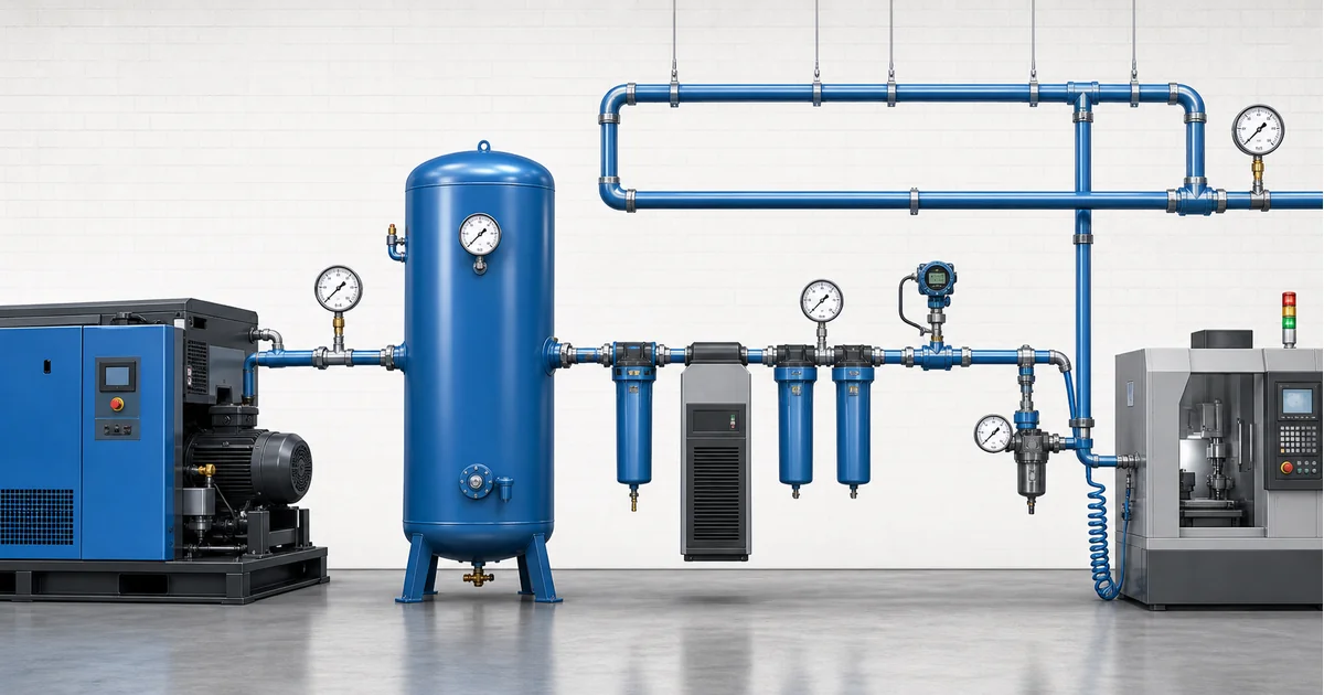
압축공기 압력계 선정은 컴프레서, 리시버, 드라이어, 필터, 배관 및 사용 지점 레귤레이터에 맞는 현장 압력계와 차압 판독을 선택하는 일입니다.
1. What compressed air pressure gauge selection should prove
Compressed air pressure gauge selection should prove whether each part of the air system has enough pressure for its actual function. A compressor discharge gauge proves what the package can produce. A receiver gauge shows stored pressure. Gauges before and after dryers or filters show whether pressure drop is normal or rising. A regulator gauge confirms the pressure delivered to pneumatic tools, valves, cylinders or packaging machines.
The Compressed Air and Gas Institute defines pressure drop as loss of pressure in a compressed air system or component due to friction or restriction. The U.S. Department of Energy sourcebook also treats leaks and unnecessary system pressure as energy problems; lower pressure reduces leakage through an opening. See the CAGI resource library and the DOE compressed air sourcebook for background.
The main keyword for this article is compressed air pressure gauge selection. Related terms include compressed air pressure drop, pneumatic system pressure gauge, filter differential pressure gauge and point-of-use air pressure monitoring.
스테인리스 압력계 보기 ->143개 이상의 공업용 게이지 탐색→2. Pressure points from compressor room to point of use
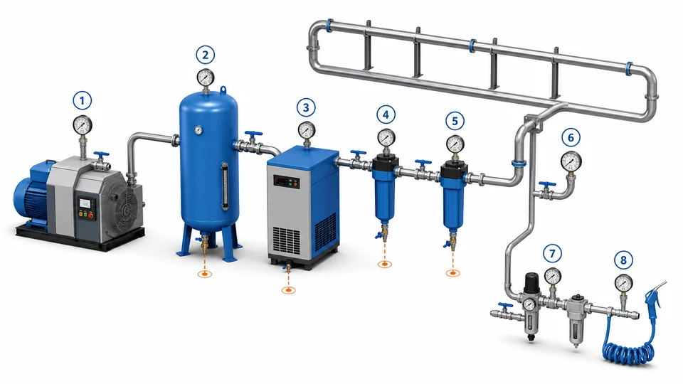
Use more than one reading when diagnosing a compressed air complaint. A low pressure report at a machine can be caused by compressor control, wet receiver pressure, dryer pressure drop, dirty filters, undersized pipe, closed valves, leaks, regulator setting or a clogged tool hose. One gauge cannot separate these causes.
| Location | What the reading checks | Gauge implication |
|---|---|---|
| Compressor discharge | Package control pressure and load/unload behavior | Range above normal control band, vibration awareness |
| Receiver outlet | Stored plant air before treatment or distribution | Easy-to-read local gauge, isolation valve |
| Dryer and filters | Pressure drop and element loading | Two gauges or differential indicator across the same component |
| Ring main / far header | Distribution pressure under production demand | Durable gauge or transmitter for trend logging |
| Point-of-use regulator | Actual pressure delivered to tools or cylinders | Small local gauge matched to regulator outlet range |
When gauge readings are compared, record compressor state, flow demand, dryer status and downstream valves. A pressure map created during clean, stable operation becomes the baseline for future maintenance.
3. Range, accuracy and construction for compressed air pressure gauges
Most factory compressed air systems operate in bar or psi ranges far below hydraulic systems, but the gauge must still match maximum allowable pressure, regulator outlet pressure and expected pulsation. A gauge whose normal reading sits near the middle of the dial is easier to read than one operating near zero or full scale. For regulator outlets, a narrow range may improve readability; for receiver or compressor discharge points, overpressure margin matters more.
Accuracy should match the decision. A general maintenance gauge may be sufficient for visual checks, while troubleshooting pressure drop across a filter or validating a regulator setting may need tighter accuracy or a calibrated digital gauge. Dial size should match viewing distance: Ø40 mm may fit a compact regulator, while Ø63-100 mm is easier for compressor rooms and headers.
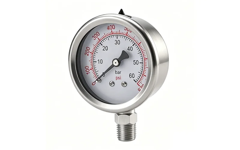
Manogauge product data lists the ZX-01-R stainless steel pressure gauge with 0-100 MPa range options, Ø40-100 mm dial sizes, 304 / 316L stainless steel material options, ±1.0 / 1.6% accuracy and G/PT/NPT 1/2 connection options. For pneumatic equipment with stronger vibration, compare the shock-resistant pressure gauge line before ordering.
압축공기 압력계 RFQ 준비 ->엔지니어가 24시간 이내 답변→4. Material, moisture and installation details
Compressed air is not always clean dry air. Condensate, compressor oil carryover, cleaning chemicals, outdoor humidity and aluminum or steel pipe debris can affect gauge service life. Brass or stainless wetted parts may both appear in pneumatic systems, but the final choice should follow air quality, condensate chemistry, plant standards and surrounding washdown or corrosion risk.
Install gauges with an isolation valve where maintenance is expected. Avoid locations where the gauge blocks a walkway, creates a snag point, or traps condensate in a way that freezes. Thread type must be specified clearly; NPT, BSP, G and metric threads are not interchangeable. For sealing risk, see the pressure gauge thread connection guide. For pulsation at compressors or fast cycling valves, review snubber and pulsation protection.
Do not assume a glycerin-filled gauge is always best. Filling can stabilize pointer movement, but it also changes temperature behavior and service assumptions. Oxygen-enriched, special gas or oil-free cleanroom air systems need separate cleanliness review.
5. What pressure readings cannot prove
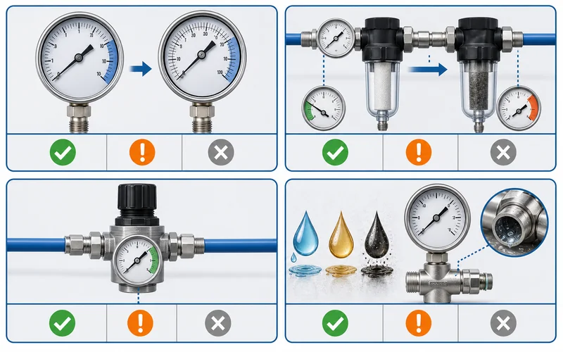
A pressure gauge does not measure flow, dew point, oil content, particle class, compressor efficiency or leak volume. Normal pressure at the receiver can exist while the farthest machine is starved during peak demand. Low pressure at a tool can come from a small hose even when the header is healthy. High pressure at the compressor can hide unnecessary energy use if regulators and leaks are compensating for poor distribution.
For high-risk or quality-critical pneumatic systems, pressure readings should be combined with flow meters, dew point monitoring, leak surveys, filter maintenance records and machine cycle data. Do not use catalog photos to infer certifications, oil-free cleanliness or safety approvals. Manogauge is a Zhejiang manufacturer with ISO 9001 quality management and export experience, but final compressed air pressure gauge selection must be confirmed against the plant standard and actual operating conditions.
6. RFQ checklist for compressed air pressure gauge selection
A useful RFQ should describe each measurement point instead of asking for a generic air gauge. Include normal pressure, maximum pressure, unit, compressor control band, dryer and filter model, regulator outlet set point, vibration level, pipe connection and viewing distance.
- State whether the gauge is for compressor discharge, receiver, dryer, filter, ring main, branch line or point-of-use regulator.
- Specify bar, psi, MPa or dual-scale dial requirements, and whether calibration documents are needed.
- Confirm dry or liquid-filled construction, dial diameter, accuracy class, case material, wetted material and window material.
- Define thread standard and mounting orientation: bottom, back, panel, valve manifold or regulator body.
- For filter pressure drop, decide whether two gauges, a differential pressure gauge or a transmitter is required.
With these details, compressed air pressure gauge selection becomes a maintenance decision based on pressure evidence, not a guess based on pipe size.
Часто задаваемые вопросы
Where should pressure gauges be installed in a compressed air system?
Use gauges at compressor discharge, receiver outlet, before and after dryers or filters, distribution headers and point-of-use regulators. The exact layout depends on the plant drawing and the maintenance question being answered.
What pressure range is best for a compressed air gauge?
Select range from normal pressure, maximum pressure and readability. The normal value should be easy to read, commonly near the middle of the dial, while receiver and compressor points still need suitable overpressure margin.
Can a pressure gauge find compressed air leaks?
A gauge can show pressure loss under demand, but it cannot measure leak volume or locate the leak. Use leak surveys, flow data and ultrasonic detection for leak confirmation.
Do filters need a differential pressure gauge?
For maintenance decisions, compare pressure before and after the same filter. This can be done with two gauges, a differential gauge or a transmitter, depending on whether local reading, alarm or trend data is required.
Should compressed air gauges be brass or stainless steel?
Match wetted material to condensate, oil carryover, plant standards and corrosion exposure. Stainless steel is often conservative for wet, outdoor or washdown areas, but the final choice should be confirmed for the actual air quality.