The process connection is a critical interface for any pressure gauge, directly impacting measurement accuracy, system safety, and long-term reliability. A mismatched thread can lead to catastrophic leaks, equipment damage, and process downtime. This technical reference provides a detailed comparison of the most common industrial pressure gauge thread standards—including NPT, BSPT, G (BSPP), Metric, and SAE—to guide engineers in making the correct selection for their specific application, from general process instrumentation to high-pressure hydraulic systems.
Fundamental Sealing Mechanisms: Taper vs. Parallel
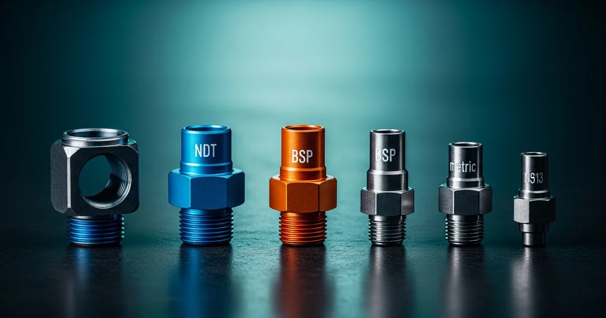
Industrial pressure gauge connections achieve a seal in one of two ways: on the threads themselves or on a separate face. Understanding this distinction is the first step in proper gauge selection.
Tapered Threads (also known as pipe threads) form a seal through metal-to-metal interference. The male and female threads are cut on a slight cone angle. As the connection is tightened, the flanks of the threads are compressed and deformed, creating a seal. This type of connection, found in NPT and BSPT standards, always requires a thread sealant to fill microscopic voids and prevent galling.
Parallel Threads (also known as straight threads) have a constant diameter along their entire length. The threads themselves serve only to provide mechanical clamping force. The seal is made by compressing a separate sealing element—such as a bonded washer, an O-ring, or a metal gasket—against a smooth, machined surface on the gauge socket or the mating port. Common parallel thread standards include G (BSPP), Metric, and SAE.
For the formal NPT reference, consult ASME B1.20.1 pipe threads.
Browse Our Pressure Gauge Catalog →Explore 143+ industrial gauge models→Tapered Thread Standards: NPT vs. BSPT (R/Rc)
NPT (National Pipe Taper) is the dominant standard in North America, defined by ASME B1.20.1. It features a 60° thread angle with flattened crests and roots. The taper rate is 1° 47’ (1.7833°), or 1 in 16 (inch per inch).
BSPT (British Standard Pipe Taper) is common in Europe, Asia, and many other regions. It is defined by standards such as ISO 7-1, EN 10226-1, and GB/T 7306.2. BSPT features a 55° Whitworth thread profile with rounded crests and roots. The male thread is designated 'R' and the female is 'Rc'.
A critical point is that NPT and BSPT threads are not interchangeable. While some sizes share the same number of threads per inch (TPI), the differing thread angles (60° vs. 55°) and thread forms will cause a mismatched connection to gall, damage threads, and create a leak path that cannot be reliably sealed, especially under pressure or vibration. Always use a thread gauge to confirm the type before installation.
BSP sealing should be checked against ISO 7-1 pipe threads where pressure-tight joints are made on the threads.
Parallel Thread Standards: G (BSPP) and Metric
G / BSPP (British Standard Pipe Parallel) threads are defined by ISO 228-1. The 'G' designation is standard. These threads require a sealing washer, typically a bonded seal (e.g., a metal washer with a vulcanized elastomer ring), which is compressed between the face of the gauge socket and the face of the mating port. This design is common for general industrial applications and is standard for gauges compliant with EN 837-1.
Metric Parallel Threads are also widely used, particularly in European equipment. The most common connection for high-quality pressure gauges is M20×1.5, often specified in EN 837-1. This connection typically seals using a profile sealing ring (e.g., made of NBR or FKM) that fits into a recess in the male port, sealing against a smooth female port face. This method provides a very reliable seal for high-pressure applications, such as those found in test benches and hydraulic systems.
Thread material and corrosion risk should be selected with the 316L stainless steel vs. brass gauge connection guide.
Request a Free QuoteOur engineers respond within 24 hours→High-Pressure Hydraulic Connections: SAE J514
Hydraulic systems, characterized by high pressure, pressure spikes, and vibration, demand more robust connection types than standard pipe threads. The SAE J514 standard defines two prevalent types for these applications.
- SAE J514 37° Flare (JIC): This connection features a straight thread for mechanical strength and a 37° conical flare on the male fitting that seats against a matching 37° cone in the female fitting. The seal is a metal-to-metal line of contact between the two cones. It is extremely common in fluid power systems worldwide.
- SAE J514 O-Ring Face Seal (ORFS): Considered one of the best connections for preventing leakage in high-vibration environments. The male fitting has a straight thread and a flat face with a groove containing an O-ring. This flat face is tightened against the flat face of the female port, compressing the O-ring to create a highly reliable seal. This design is often specified for critical mobile equipment and industrial hydraulic power units.
Tri-clamp and hygienic connections are covered in the sanitary pressure gauge selection guide.
Sealant Selection and Connection Orientation
The choice of sealant is dictated entirely by the thread's sealing mechanism.
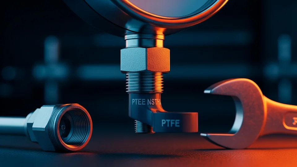
- For Tapered Threads (NPT, BSPT): A sealant is mandatory. High-density PTFE tape (3-4 wraps, applied clockwise on the male thread) or a suitable liquid/paste PTFE thread sealant is required. For applications with vibration, an anaerobic thread sealant that cures in the absence of air can provide a more robust, locked seal. Always leave the first 1-2 threads bare to prevent sealant from entering the process media.
- For Parallel Threads (G/BSPP, Metric, SAE): Never use thread sealant. The seal is made by the gasket, bonded seal, or O-ring. Applying tape or paste can prevent the sealing faces from mating correctly, causing a leak. A light machine oil may be applied to the threads to prevent galling during tightening, but it does not act as a sealant.
Connection orientation refers to the location of the process connection on the gauge case. Lower Mount (or bottom mount) connections extend from the bottom of the gauge and are used for vertical pipe runs or surface mounting. Back Mount connections (either center-back or lower-back) extend from the rear of the gauge and are ideal for panel mounting, allowing the gauge to be read flush against an instrument panel.
Final mounting checks belong in the pressure gauge installation best practices.
Key takeaways
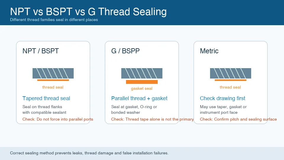
- Tapered threads (NPT, BSPT) seal on the thread flanks and require a sealant; they are not interchangeable due to differing thread angles (60° vs 55°).
- Parallel threads (G/BSPP, Metric) have a constant diameter and seal using a separate bonded seal, gasket, or O-ring against a machined face.
- For high-vibration hydraulic systems, SAE J514 connections like 37° Flare (JIC) or O-Ring Face Seal (ORFS) provide superior leak resistance.
- Never use thread sealant on parallel or SAE connections; the seal is mechanical and sealant can interfere with proper seating.
- Always verify thread type, size, and pitch with a thread gauge before installation to prevent dangerous leaks and equipment damage.
Related products
- General Pressure Gauge - Radial (ZX-08-R) — 0–40 MPa
- Stainless Steel Pressure Gauge - Radial (ZX-01-R) — 0–100 MPa
- Liquid-Filled Pressure Gauge - Radial (ZX-06-R) — 0–60 MPa
Frequently asked questions
What is the difference between NPT and BSP pressure gauge connections?
NPT (National Pipe Thread, ASME B1.20.1) is the US tapered thread standard, sealing on the threads with PTFE tape. BSP (British Standard Pipe) comes in two variants: BSPT (tapered, seals on threads) and BSPP (parallel, seals on a flat face with a washer or O-ring). The 60° NPT thread profile differs from BSP's 55° profile — they are NOT interchangeable even when the same nominal size fits.
What thread size is standard for a 100mm industrial pressure gauge?
For 100mm (4-inch) dial gauges, the standard connection is G1/2 B (BSPP, per EN 837-1) or 1/2 NPT depending on region. For 63mm (2.5-inch) gauges, G1/4 B or 1/4 NPT is standard. Always specify the full connection designation — '1/2 NPT' or 'G1/2 B' — not just the nominal size, since the thread system differs.
How do I identify whether a pressure gauge has NPT or BSP threads?
Use thread identification gauges (Go/No-Go) for definitive identification. Quick field check: NPT has a 60° thread angle and tapers at 1/16 inch per inch; BSP has a 55° thread angle. NPT threads appear slightly coarser (fewer threads per inch at the same nominal size). Always verify with gauges before installation — a mismatched connection may appear to seal initially but will leak under pressure cycling.
Can I use PTFE tape on BSP parallel (BSPP / G thread) connections?
No. BSPP (G thread) connections seal on the flat face with an O-ring or fiber washer — PTFE tape on the thread does not provide the required seal and may prevent the flat-face seal from seating correctly. For BSPT (tapered BSP), PTFE tape or anaerobic thread sealant is acceptable. For NPT, PTFE tape is the standard sealant.
What is the correct torque for installing a pressure gauge connection?
For G1/4 B on 63mm gauges: 10–20 N·m (7–15 ft·lb). For G1/2 B on 100mm gauges: 20–40 N·m (15–30 ft·lb). For 1/2 NPT: 20–35 N·m (15–26 ft·lb). Always apply torque to the hex flats on the gauge socket, never to the case — torquing the case can deform the Bourdon tube internals. Never use thread sealant on BSPP flat-face connections.
What connection type should I use for a pressure gauge on a high-purity or hygienic system?
Specify tri-clamp (TC / DIN 32676) or aseptic connections for food, pharmaceutical, or high-purity applications. Threaded connections (NPT, BSP) cannot be adequately cleaned and create crevices where bacteria or contaminants can harbor. For instrumentation in these industries, all process-wetted connections should be tri-clamp or equivalent hygienic fittings per EHEDG, 3-A, or ASME BPE standards.