
Solid-front pressure gauge selection is a safety decision, not only a catalog preference. In high-pressure gas, steam, petrochemical, compressor, hydraulic and hazardous-area services, the pressure element inside a mechanical gauge can fail under overpressure, corrosion, fatigue or pulsation. A solid-front safety case places a rigid wall between the pressure element and the dial window, then provides a blow-out back so released energy is directed away from the operator side. This guide explains when that case design matters, what ASME B40.100 and EN 837-1 language can and cannot prove, and what data should be included in a technical RFQ.
What a solid-front pressure gauge is
Solid-front pressure gauge selection starts with the case construction. In a standard open-front process gauge, the dial window is closer to the Bourdon tube, socket and movement. In a solid-front safety gauge, a metal baffle wall separates those pressure-containing parts from the front window. If the Bourdon tube ruptures, the case should vent through the rear blow-out back rather than toward the person reading the dial.
This design is commonly reviewed for compressed gases, oxygen-compatible systems, high-pressure hydraulic units, steam headers, refineries, chemical dosing skids, test benches and compressor packages. It is especially relevant when the stored energy of the medium is high, when the medium is hazardous, or when operators must stand in front of the gauge during inspection.
The ASME B40.100 pressure gauge standard covers terminology, definitions, testing and safety considerations for dial and digital pressure indicating gauges and related accessories. Treat that standard as a framework for specification language; final suitability still depends on the real pressure, medium, temperature and installation layout.
Review Stainless Steel Safety Gauge Options ->Explore 143+ industrial gauge models→How the safety case controls failure direction
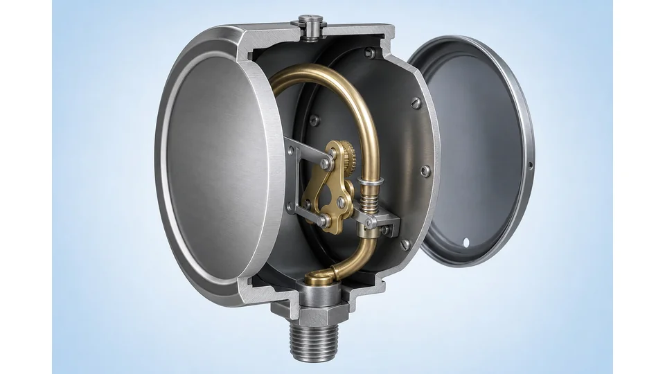
A solid-front safety case does not stop every failure. Its purpose is to control the direction of the highest-risk release. The baffle wall protects the front window area, while the rear blow-out panel creates a preferred relief path. The gauge should be mounted so the rear path is not blocked by a wall, bracket, insulation box or another instrument.
The concept is easiest to understand as three layers: pressure element containment, operator-side separation and rear pressure relief. Each layer has to remain intact after installation. A blocked rear panel, missing blow-out device, cracked window, wrong case material or improvised panel screw can defeat the safety concept.
| Safety feature | Engineering purpose | RFQ wording |
|---|---|---|
| Solid front baffle wall | Separates pressure element from operator-facing window. | Request solid-front safety pattern case. |
| Blow-out back | Provides a rear relief path if the pressure element fails. | Confirm full blow-out back or rear blow-out device. |
| Safety window | Reduces window-fragment risk compared with ordinary glass. | State laminated safety glass or equivalent requirement. |
| Correct orientation | Keeps the relief path away from people and obstructions. | State panel, pipe or bracket mounting direction. |
When solid-front pressure gauge selection is justified
Solid-front pressure gauge selection is most defensible when the consequence of a gauge failure is more severe than the small cost difference from a standard case. High-pressure gas is a common trigger because compressed gas stores energy. Steam and hot oil add thermal risk. Corrosive media can thin the Bourdon tube. Pulsating pump or compressor discharge can accelerate fatigue. Hazardous-area service can also require a conservative case design even when normal pressure is moderate.
Start with the service data: medium, normal pressure, maximum pressure, pressure cycling, vibration, ambient exposure and whether the operator reads the gauge at close range. For aggressive, viscous or crystallizing media, add diaphragm seal review. For pulsation, compare the pressure gauge snubber pulsation protection guide. For overpressure events, review the pressure gauge overpressure protection guide.
Manogauge catalog data includes stainless steel pressure gauges with 0-100 MPa range options, Ø40-100 mm dial sizes, 304 / 316L stainless steel construction and G/PT/NPT 1/2 connections. Those data points help shortlist a gauge family, but a safety-case request must still specify the required case pattern and documentation.
Prepare a Safety Gauge RFQ Checklist ->Our engineers respond within 24 hours→ASME B40.100, EN 837-1 S3 and what standards do not prove

Standards language helps buyers and suppliers discuss the same safety features. ASME B40.100 is often used in North American and export RFQs for pressure gauge terminology, dimensions, testing and safety considerations. EN 837-1 is often referenced for Bourdon tube gauges in European-style specifications, including safety pattern concepts such as blow-out devices and S3 solid-front construction.
However, a standard reference alone does not prove compatibility with a specific process. It does not confirm that 316L wetted parts resist the medium, that a diaphragm seal is unnecessary, that the rear relief path is unobstructed, that the gauge range is readable, or that certificates match the purchasing contract. It also does not replace a site hazard review for oxygen, hydrogen, sour gas, explosive atmospheres or toxic media.
Use wording such as: solid-front safety pressure gauge, rear blow-out back, laminated safety window, ASME B40.100 or EN 837-1 S3 reference, wetted material, connection thread, range, accuracy class, fill fluid, case venting and calibration certificate. Avoid asking only for a safe gauge; that phrase is too vague for purchasing and inspection.
Installation details that can weaken a safety gauge
A safety case can be undermined by poor installation. The rear blow-out path needs clearance. The gauge should not be mounted with its back against a plate unless the panel design provides a suitable relief opening. The socket should not carry pipe stress, and the case should not be used as a handle when tightening the connection. If the gauge is liquid-filled, fill fluid temperature, case venting and chemical compatibility must be reviewed.
Accessories need the same scrutiny. A valve allows maintenance isolation but can hide live pressure if closed unintentionally. A snubber can reduce pointer oscillation but may clog. A diaphragm seal isolates corrosive or viscous media but adds temperature, fill-fluid and response-time questions. A siphon protects a steam gauge from temperature but does not replace pressure relief design.
For high-pressure, hazardous or critical service, the project engineer should define orientation, bracket support, vent clearance, lock-open or lock-closed valve rules, calibration interval and replacement criteria. A stable pointer is useful local indication; it is not proof that the pressure system is safe.
Solid-front pressure gauge RFQ checklist
A complete RFQ for solid-front pressure gauge selection should describe the process rather than only the dial range. Include medium, normal pressure, maximum pressure, pulsation, temperature, ambient exposure, mounting position, thread, wetted material, case material, safety case requirement, window material, liquid filling, accessories, certificates and target standards.
- State whether the medium is liquid, steam, compressed gas, oxygen, hydrogen, ammonia, refrigerant, hydraulic oil or corrosive chemical.
- Confirm if the rear blow-out back has open clearance after installation.
- Specify NPT, BSP, G or metric thread, bottom or back connection, and any panel-mount requirement.
- Ask for drawings when the gauge sits inside a cabinet, behind insulation, or near an operator walkway.
- For Manogauge OEM or export projects from Zhejiang, China, request the drawing, material statement, calibration document and packaging requirement before sample approval.
With these inputs, suppliers can quote a solid-front pressure gauge that matches the hazard level, not just the pressure number printed on the dial.
Key takeaways
- A solid-front pressure gauge uses a baffle wall and rear blow-out path to reduce operator-side release risk.
- ASME B40.100 and EN 837-1 S3 are useful specification references, but they do not replace process compatibility checks.
- The rear blow-out back must remain unobstructed after installation.
Frequently asked questions
What is a solid-front pressure gauge?
A solid-front pressure gauge has a rigid baffle wall between the pressure element and the front window, plus a rear blow-out path intended to direct release away from the operator side if the element fails.
When should a solid-front safety case be specified?
Specify it for high-pressure gas, steam, hazardous media, corrosive service, strong pulsation, compressor or pump discharge, and any point where an operator reads the gauge close to the dial.
Does ASME B40.100 automatically mean the gauge is safe for my process?
No. ASME B40.100 provides terminology, testing and safety considerations, but the project still has to confirm medium compatibility, pressure range, temperature, accessories, installation orientation and certificates.
What clearance is needed behind a blow-out back?
The rear blow-out path should not be blocked by panels, walls, brackets, insulation or other instruments. Exact clearance should be confirmed with the gauge drawing and site layout.