
District heating pressure gauge selection means specifying local pressure gauges, differential pressure gauges and temperature instruments for the heat exchanger station that connects a district energy network to a building loop. The goal is not simply to add a dial. Correct instruments help operators compare primary and secondary pressure, confirm pump and strainer condition, protect plate heat exchangers, and document whether the station is operating within the limits set by the network owner and building engineer.
What district heating pressure gauge selection has to prove
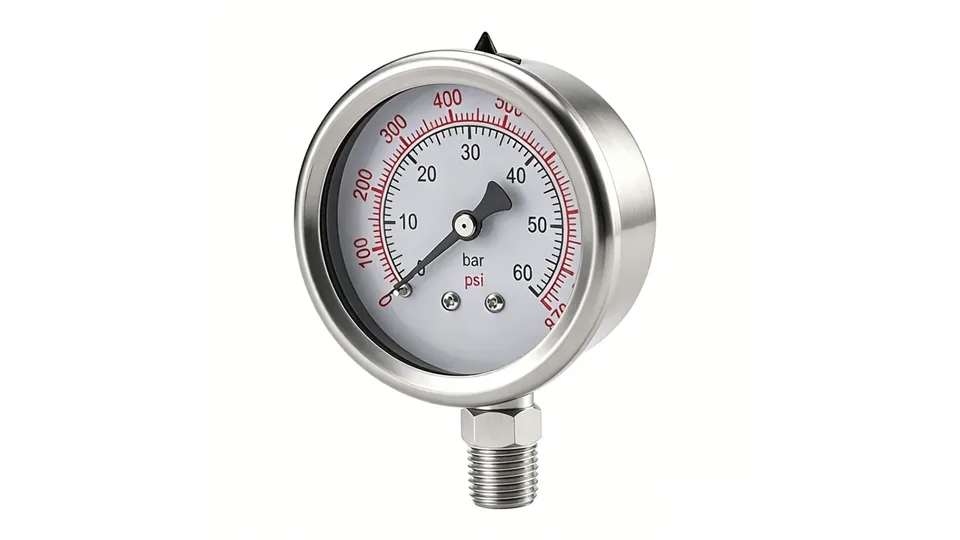
District heating pressure gauge selection starts with the function of the substation. A district heating heat exchanger station transfers heat from the network primary side to a building secondary loop, usually through a plate heat exchanger. Pressure readings help operators see whether the network supply is available, whether the secondary pump is creating enough circulation, and whether the station is developing abnormal pressure drop.
Current district energy work is moving toward lower temperatures, renewable heat and better controls. The IEA notes that upgrades to pipes, substations and controls are important for greater flexibility and efficiency in district heating networks. See the IEA commentary on opportunities for district heating in the changing energy landscape. For an instrument buyer, that means pressure gauges should support troubleshooting and commissioning, not just meet a minimum price.
A local dial should be readable during routine inspection, but final limits must come from the network company, station designer, equipment supplier and applicable local code.
Review Stainless Steel Gauge OptionsExplore 143+ industrial gauge models→Primary side, secondary side and differential pressure points
The most useful measuring points are normally arranged around the primary inlet and return, the secondary supply and return, the pump discharge and strainers. Pressure before and after a strainer can show whether debris is creating excessive loss. Primary and secondary readings help separate a network-side problem from a building-side circulation problem.
| Point | What it helps check | Instrument note |
|---|---|---|
| Primary supply and return | Network availability and pressure boundary at the station | Confirm maximum network pressure and temperature before choosing range. |
| Secondary supply and return | Building-loop circulation and pump condition | Use a readable range around normal operating pressure. |
| Across strainer or filter | Clogging trend and maintenance timing | A differential pressure gauge or two local gauges can be used. |
| Plate heat exchanger ports | Unexpected pressure drop or isolation-valve errors | Use service valves so gauges can be isolated or replaced safely. |
| Expansion and safety group | Static fill pressure and relief-valve context | Do not use a gauge reading alone to prove relief capacity. |
For related fundamentals, compare the pressure gauge installation best practices and the differential pressure gauge selection guide.
Range, temperature and material checks for district heating pressure gauges
Heat-transfer water can be hot, treated and sometimes dirty. The gauge range should cover normal operating pressure, pump head, static fill pressure, safety-valve setting and credible transients, while still keeping normal readings in a useful part of the dial. Do not copy a 0-10 bar or 0-16 bar gauge from another station unless the network pressure class and building loop are actually similar.
Temperature is equally important. A Bourdon tube gauge may need a pigtail siphon, cooling element or remote mounting if the process temperature at the gauge socket exceeds the instrument limit. For high-temperature heating water, confirm the ambient temperature, heat radiation from insulated pipes, isolation valve type and whether a bimetal thermometer or temperature transmitter should be specified at the same point.
Wetted parts should match water treatment chemistry, oxygen ingress risk and corrosion expectations. Brass internals may be acceptable in many closed heating loops, while stainless steel wetted parts are often preferred for harsher water chemistry, outdoor cabinets or owner standards. Manogauge product references include stainless steel pressure gauges and temperature-pressure gauges, but the final material and range must be verified against the project specification.
Prepare a District Heating Gauge RFQOur engineers respond within 24 hours→Inspection, commissioning and failure clues
During commissioning, technicians compare gauge readings with pump curves, valve positions, heat-meter data and controller signals. A stable pressure profile does not prove heat transfer performance, but it can quickly show closed valves, undersized bypasses, blocked strainers, air pockets, failed expansion vessels or incorrect pump speed. KROHNE describes transfer-station instrumentation as monitoring flow, pressure and temperature in an energy transfer station, which is a useful reminder that pressure is one part of the measurement set.
In service, trend matters more than one isolated number. If a secondary loop that normally runs at a steady pressure begins to drift, the cause may be leakage, air removal, expansion tank failure or a make-up water issue. If differential pressure across a strainer rises, cleaning may be needed before flow becomes restricted. If the primary-side pressure is normal but the secondary side is unstable, the building loop deserves attention.
For traceable inspection decisions, see the pressure gauge export certifications guide. A field gauge should be compared with a suitable reference when readings affect safety, billing disputes or acceptance tests.
What a pressure gauge cannot prove in a heat exchanger station
A pressure gauge cannot prove heat quantity, flow rate, heat exchanger cleanliness, water chemistry, pump efficiency, relief-valve capacity or compliance with a district heating contract. It also cannot show whether the return temperature is low enough for network efficiency. Those judgments need flow measurement, temperature data, heat meters, water-quality checks, controller records and engineering review.
District heating pressure gauge selection should therefore be treated as a supporting layer in a monitored substation. Danfoss notes that pressure, differential pressure, temperature and flow are integrated and automatically controlled on many substations; that integrated view is the correct mindset. Local gauges help technicians, but they do not replace the controller, heat meter, safety devices or the network operator requirements.
Manogauge is a Zhejiang-based pressure gauge manufacturer with industrial gauge production experience for export markets. For district heating projects, the RFQ should still list the real station data instead of relying on a generic catalog item.
RFQ checklist for district heating gauges
A practical RFQ should include the measuring point, normal and maximum pressure, temperature at the gauge socket, connection thread, mounting orientation, dial diameter, scale units, accuracy class, wetted material, case material, window material, isolation valve requirement, calibration document requirement and expected quantity. If the gauge is installed outdoors or in an underground station, add ingress protection, condensation risk and vibration details.
For district heating substations, the buyer should also state whether the point is primary or secondary side, whether the medium is treated water or glycol mixture, whether the gauge will be used for commissioning only or permanent local indication, and whether a pressure transmitter is also required for BMS or SCADA. The conclusion is simple: district heating pressure gauge selection is reliable only when the dial, material and installation details are tied to the actual heat exchanger station.
District-heating gauges must be matched to the side of the heat exchanger. Primary network water can have materially higher pressure and temperature than the building-side circuit, while a secondary pump loop may need a smaller range for useful resolution. Mark the pressure class, normal operating point and maximum credible pressure for each port. If differential pressure across a strainer or control valve is important, use two identified pressure points or a suitable DP instrument rather than inferring it from unrelated gauges.
Hot water also changes the installation design. Verify the temperature at the gauge, use a cooling element or siphon where required by the equipment design, and provide isolation for calibration. Check thermal expansion, water treatment chemistry, oxygen exposure and the material of adapters and seals. A stainless case protects the outside; it does not by itself establish compatibility with treated district-heating water.
A district heating pressure gauge selection record should name primary or secondary loop, pressure and temperature envelope, connection standard, dial size, accuracy, mounting, insulation clearance and maintenance access. The final range and accessories require confirmation from the substation designer and gauge manufacturer.
At commissioning, record pressure with pumps running and stopped, and note the heat-exchanger control-valve position. This distinguishes static fill pressure from circulating pressure and makes later strainer or pump diagnosis easier. Protect the instrument from direct hot-water exposure where the installation design calls for a siphon or cooling section, and leave enough clearance to read and calibrate it after insulation is installed.
Do not use a secondary-loop gauge to verify primary network pressure, and do not infer heat-transfer performance from pressure alone. Flow, temperature difference, valve authority and exchanger fouling require their own measurements and engineering review.
How to turn hot-water temperature, static head, pump differential pressure, corrosion and readable outdoor installation into a purchase specification
A useful specification begins with the process rather than the catalogue name. Record the normal operating value, the minimum and maximum credible values, the upset condition, the medium composition, the process temperature and the way the instrument will be mounted. Then state what the operator must see: a stable local indication, a peak, a differential, a switch point or a value that will be compared with a calibrated reference. This distinction matters because a gauge can be mechanically accurate yet unsuitable when its sensing element, connection or response is wrong for the installation.
Separate the continuously expected condition from the short duration event. For hot-water temperature, static head, pump differential pressure, corrosion and readable outdoor installation, the short event may be more important than the average reading, but it should not be handled by quietly selecting a larger dial range. A larger range reduces readability and can increase the error at the operating point. Conversely, a range selected too tightly can expose the element to repeated overload. Document the expected cycle, the allowable overpressure and the required indication during start-up, shutdown and cleaning. If those values are unavailable, the final range must remain a site-engineering decision.
Installation details deserve the same attention as the gauge body. Confirm whether the tapping point is exposed to vibration, pulsation, water hammer, thermal shock, condensation, washdown or a corrosive atmosphere. Provide an isolation valve where safe maintenance requires it, and consider a gauge cock, siphon, snubber, diaphragm seal or remote mounting only when its effect on response and calibration is understood. The connection thread must match the mating component; NPT, BSP/G and metric threads are not interchangeable simply because their nominal size appears similar. Never force a mismatched thread or use sealant to compensate for the wrong standard.
Before release, ask for the evidence that is actually needed for the job: dimensional drawing, wetted-material declaration, accuracy statement, calibration method, pressure test requirement and packing or cleanliness instruction. Do not request certificates as a substitute for checking the process chemistry or hazard classification. Standards and customer specifications may define construction, testing or documentation, but they do not automatically prove compatibility with every concentration, temperature or cleaning cycle. The responsible engineer should reconcile the instrument data sheet with the P&ID, valve arrangement and maintenance procedure.
Commissioning should establish a baseline. With the process in a known condition, record the gauge indication, reference reading, temperature, pump or compressor state and any pointer oscillation. Recheck after the system reaches normal load and after a controlled shutdown. A drifting zero, a slow response, a blocked impulse path or an unexpectedly quiet pointer can all be failure signals rather than evidence of good performance. Trend records also make later replacement decisions more reliable because the next instrument can be specified from observed service instead of a generic catalogue assumption.
The practical conclusion for hot-water temperature, static head, pump differential pressure, corrosion and readable outdoor installation is to select the complete measurement chain: sensing element, wetted material, range, accuracy, connection, mounting, protection accessory and documentation. The product photograph on this page identifies the real Manogauge gauge construction used as a reference; it is not proof that the same configuration is correct for every medium or pressure. Confirm the final model, dimensions and available options against the current data sheet before purchase.
Review note: Treat the published values as a framework for engineering review, not as a universal approval. The final choice should be checked against the current Manogauge data sheet, the project P&ID and the site risk assessment. Record any deviations, accessory settings and inspection interval in the maintenance file so that a replacement gauge is not selected from a photograph alone.
Key takeaways
- Select district heating gauges by measuring point: primary side, secondary side, strainer DP, pump discharge and expansion group.
- Temperature protection is as important as pressure range when gauges are installed near hot water pipes.
- A pressure reading supports troubleshooting, but it does not prove heat quantity, flow, water chemistry or safety-valve capacity.
Related buyer pages
Liquid-filled pressure gauge supplierGlycerine-filled gauges for booster pump sets and substation pressure points with pulsation.
Bimetal thermometer manufacturerPair the pressure points with supply and return bimetal thermometers and matched thermowells.
Stainless steel pressure gauge manufacturerStainless cases and 304/316L wetted parts for treated hot water and outdoor substations.
Related reading
- Differential Pressure Gauge Selection: Range & Filters
Select a differential pressure gauge for filters and process lines: compare DP range, static pressure, overpressure protection, accuracy and installation.
- Filter Differential Pressure Gauge: Range, Alarm, Changeout
Choose a filter differential pressure gauge from clean DP, changeout DP and flow: DP span, alarm setting, port layout, wetted materials and cleaning limits.
- Bimetal Thermometer & Thermowell: 316L, -40–400°C
Select a bimetal thermometer and thermowell for steam, hot water or thermal oil: compare 316L materials, insertion length, temperature and vibration.
- Nitrogen Blanketing Pressure Gauge Selection
Nitrogen blanketing pressure gauge selection for low-pressure storage tanks: range, capsule gauges, regulators, vents, oxygen-deficiency risk and RFQ checks.
- Compressed Air Pressure Gauge: bar/psi Selection Guide
Choose compressed-air gauges in bar or psi for compressors, receivers, filters and point-of-use regulators; compare range, accuracy and moisture risks.
Frequently asked questions
What pressure range should a district heating gauge use?
There is no universal range. Use the station design pressure, normal operating pressure, pump head, safety-valve setting and maximum network pressure to choose a readable range with enough margin.
Do district heating pressure gauges need stainless steel wetted parts?
Not always. Brass or copper alloy wetted parts may suit many closed heating loops, but stainless steel is safer for harsh water chemistry, outdoor stations, owner standards or uncertain corrosion risk.
Where should a differential pressure gauge be installed in a heat exchanger station?
Common locations are across a strainer, filter, control valve or heat exchanger section where pressure loss indicates fouling, blockage or control problems. Final locations depend on station design.
Can one pressure gauge prove a heat exchanger station is working correctly?
No. Pressure is only one signal. Flow, supply and return temperature, heat-meter data, water chemistry, pump state and controller records are needed for a complete judgment.
What should be included in a district heating gauge RFQ?
List measuring point, pressure range, temperature, medium, thread, mounting orientation, dial size, scale units, accuracy, wetted material, case material, isolation valve and calibration documents.