Chilled water DP monitoring is the practice of measuring differential pressure across supply-return headers, pumps, filters, coils and heat exchangers in an HVAC chilled-water loop. It helps facility teams keep variable-speed pumps stable, confirm whether a remote coil has enough pressure, detect clogged strainers, and separate hydraulic problems from chiller or control-valve issues. This guide explains where pressure gauges and differential pressure transmitters belong, how to choose range and wetted materials, and what the readings cannot prove without flow, valve-position and commissioning data.
What chilled water DP monitoring means in HVAC plants
Chilled water DP monitoring compares pressure at two points in a hydronic cooling system. A differential pressure transmitter reports the difference directly for building automation, while two local pressure gauges let technicians compare supply and return readings during inspection. Both methods answer a hydraulic question: is enough pressure available at this location, and is a component creating more pressure drop than expected?
In variable-flow HVAC systems, pump speed is often controlled from differential pressure or valve-position logic. ASHRAE Guideline 36 material discusses differential-pressure-controlled chilled-water loops and plant reset logic; see the public ASHRAE Guideline 36 addendum on chilled-water plant reset. A gauge alone does not optimize the plant, but it gives field visibility when a BAS value looks wrong.
Use local indication for commissioning, maintenance rounds and troubleshooting. Use a transmitter when the signal must drive alarms, trend logs or pump control. The two are complementary rather than interchangeable.
Compare Differential Pressure Gauge OptionsExplore 143+ industrial gauge models→Where to place pressure gauges and DP transmitters
The best measurement point depends on the question. Remote supply-return DP near the hydraulically critical coil helps pump control. Pump suction and discharge gauges help verify pump head and suction conditions. Differential pressure across strainers, side-stream filters or plate heat exchangers helps detect fouling. Chiller evaporator pressure drop can support commissioning, but it should be interpreted with flow and manufacturer data.
| Measurement location | Typical purpose | Instrument choice |
|---|---|---|
| Remote supply and return mains | Confirm available pressure at critical zones | DP transmitter for BAS plus test ports |
| Pump suction and discharge | Check pump head, suction pressure and abnormal restriction | Two pressure gauges or pressure transmitters |
| Strainer or filter | Detect clogging before flow drops | DP gauge or DP transmitter |
| Chiller evaporator or heat exchanger | Compare pressure drop with commissioning data | Gauge pair or DP transmitter with isolation valves |
For instrument fundamentals, compare the differential pressure gauge selection guide and the pressure transmitter vs pressure gauge selection guide.
Choose range, accuracy and wetted materials for chilled water DP monitoring
Chilled-water loops usually operate at moderate pressure, but the useful differential may be much smaller than the static line pressure. If a system runs near 6 bar static pressure and the useful differential is only 20-80 kPa, a full-line pressure gauge cannot show small control changes clearly. A DP transmitter or DP gauge with an appropriate low differential range gives better resolution.
Confirm maximum static pressure, expected pump head, normal DP setpoint, cleaning pressure, test pressure and freeze-protection fluid. Glycol blends, water treatment chemicals and oxygen ingress can affect wetted material choices. Stainless steel wetted parts are often preferred where corrosion risk or water treatment chemistry is uncertain; brass may be acceptable only after compatibility is confirmed.
Accuracy class should match the decision. A commissioning instrument may need tighter accuracy than a local trend indicator. For general selection logic, review pressure gauge accuracy class selection and 316L stainless steel vs brass wetted parts.
Prepare an HVAC Pressure Instrument RFQOur engineers respond within 24 hours→Installation details that keep readings useful
Pressure taps should be accessible, stable and protected from turbulence where practical. Near pump discharges, elbows, control valves and partially closed balancing valves, the reading may fluctuate or represent local velocity effects rather than the broader loop condition. Isolation valves, drain or vent provisions and clear labels make calibration and replacement safer.
For a DP transmitter, keep impulse lines short and protected, avoid trapped air where it distorts a liquid reading, and mount the manifold so technicians can zero, isolate and equalize the transmitter. For local pressure gauges, choose a dial size that technicians can read from the normal service position and protect the movement from vibration if installed near pump skids.
These practices align with broader pressure gauge installation best practices and centrifugal pump pressure gauge selection.
What chilled water pressure readings cannot prove
A pressure or DP reading cannot prove flow by itself. A coil with a high differential may still have low flow if a valve, strainer or balancing device is restricting the branch. A low differential may be normal at low load if the control sequence has reset pump pressure downward. A stable gauge also cannot prove that sensors are calibrated, control valves are authority-correct, or the chiller evaporator is within its flow limits.
Do not use chilled water DP monitoring as a substitute for commissioning. Final acceptance should compare pressure, flow, valve position, pump speed, temperature difference, air-side load and the approved control sequence. In large campuses, district cooling plants or critical facilities, the engineer should verify sensor locations and ranges against the hydraulic model and TAB report.
Manogauge can support local indication and pressure instrument selection from Zhejiang manufacturing, but project data must still come from the building engineer: fluid, glycol percentage, pressure class, temperature, range, thread or flange, IP rating, vibration level and documentation needs.
RFQ checklist for chilled water pressure instruments
An RFQ for chilled water instruments should describe the measurement purpose before listing model numbers. A supplier can only recommend the right pressure gauge, DP gauge or transmitter when the hydraulic question is clear.
- State the point: remote loop DP, pump suction-discharge, filter pressure drop, evaporator pressure drop or local indication only.
- Provide static pressure, expected differential pressure, maximum pump head and test pressure.
- Confirm fluid: water, glycol percentage, corrosion inhibitor, treatment chemicals and operating temperature.
- Specify connection, isolation valve or manifold requirement, dial size, output signal, IP rating and mounting position.
- Ask what the instrument cannot prove without flow or commissioning data.
With these inputs, chilled water DP monitoring becomes a useful maintenance and control signal rather than a decorative number on the pipe.
Use the design flow condition when interpreting chilled-water DP. A pump differential pressure measured at zero flow is not the same as the available DP at the index circuit. Record supply and return temperatures, valve position, pump speed and flow whenever a baseline is taken. If the system uses variable-speed pumping, trend DP with flow rather than treating one pressure value as a permanent setpoint. A blocked strainer, closed isolation valve or air pocket can create a convincing but misleading reading.
Choose the DP span from the clean operating signal and the maximum credible differential, with resolution at the control point. For example, a 0–100 kPa instrument may be unsuitable if normal control is 5–10 kPa and the useful change is only 1 kPa; a smaller span may read the condition better if overpressure protection is adequate. Confirm glycol concentration, minimum temperature, seals and connection materials, especially in a machine room with condensation.
For reliable chilled water differential pressure monitoring, document port locations, elevation, balancing-valve state, sensor orientation, range, accuracy and commissioning baseline. A gauge or transmitter indicates pressure difference at its ports; it does not by itself prove flow, heat transfer, valve authority or water quality.
Set a repeatable baseline by recording the same ports, flow, pump speed and valve position. For a 20 kPa design DP, an alarm at 30 kPa might indicate a dirty strainer, but only if flow has not simultaneously changed. Trend the signal with the control system and retain the commissioning condition so later troubleshooting compares like with like. Equalising or venting a sensor line should follow the instrument maker instructions to avoid trapping air or releasing water.
When a transmitter and local gauge disagree, check elevation, impulse tubing, zero, isolation valves and calibration before changing the range. The HVAC designer should define the control target; the instrument supplier confirms the pressure, temperature and material limits.
How to turn design flow, differential range, sensor location, balancing valves and commissioning data into a purchase specification
A useful specification begins with the process rather than the catalogue name. Record the normal operating value, the minimum and maximum credible values, the upset condition, the medium composition, the process temperature and the way the instrument will be mounted. Then state what the operator must see: a stable local indication, a peak, a differential, a switch point or a value that will be compared with a calibrated reference. This distinction matters because a gauge can be mechanically accurate yet unsuitable when its sensing element, connection or response is wrong for the installation.
Separate the continuously expected condition from the short duration event. For design flow, differential range, sensor location, balancing valves and commissioning data, the short event may be more important than the average reading, but it should not be handled by quietly selecting a larger dial range. A larger range reduces readability and can increase the error at the operating point. Conversely, a range selected too tightly can expose the element to repeated overload. Document the expected cycle, the allowable overpressure and the required indication during start-up, shutdown and cleaning. If those values are unavailable, the final range must remain a site-engineering decision.
Installation details deserve the same attention as the gauge body. Confirm whether the tapping point is exposed to vibration, pulsation, water hammer, thermal shock, condensation, washdown or a corrosive atmosphere. Provide an isolation valve where safe maintenance requires it, and consider a gauge cock, siphon, snubber, diaphragm seal or remote mounting only when its effect on response and calibration is understood. The connection thread must match the mating component; NPT, BSP/G and metric threads are not interchangeable simply because their nominal size appears similar. Never force a mismatched thread or use sealant to compensate for the wrong standard.
Before release, ask for the evidence that is actually needed for the job: dimensional drawing, wetted-material declaration, accuracy statement, calibration method, pressure test requirement and packing or cleanliness instruction. Do not request certificates as a substitute for checking the process chemistry or hazard classification. Standards and customer specifications may define construction, testing or documentation, but they do not automatically prove compatibility with every concentration, temperature or cleaning cycle. The responsible engineer should reconcile the instrument data sheet with the P&ID, valve arrangement and maintenance procedure.
Commissioning should establish a baseline. With the process in a known condition, record the gauge indication, reference reading, temperature, pump or compressor state and any pointer oscillation. Recheck after the system reaches normal load and after a controlled shutdown. A drifting zero, a slow response, a blocked impulse path or an unexpectedly quiet pointer can all be failure signals rather than evidence of good performance. Trend records also make later replacement decisions more reliable because the next instrument can be specified from observed service instead of a generic catalogue assumption.
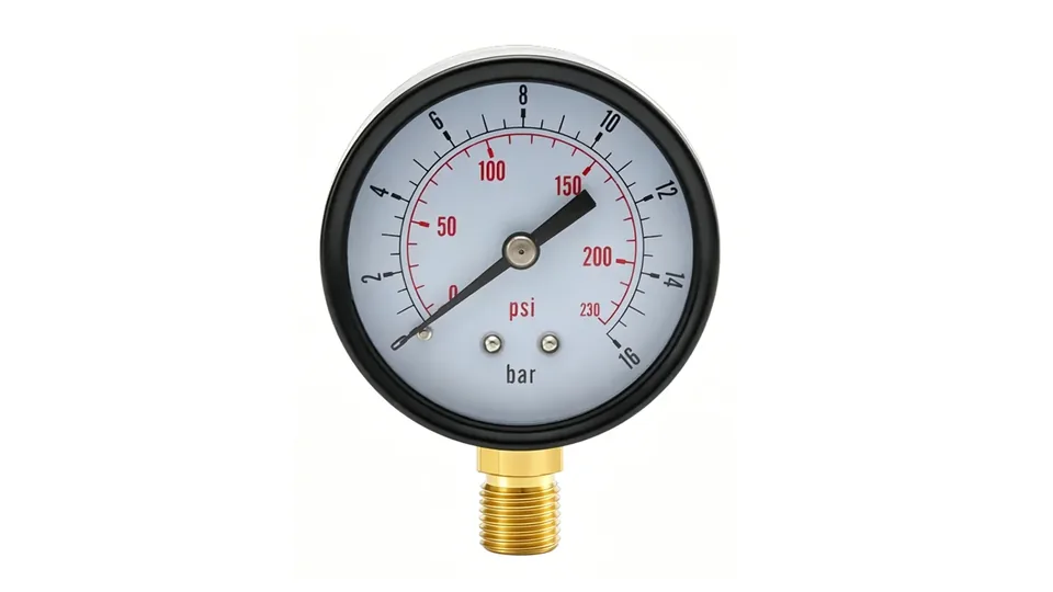
The practical conclusion for design flow, differential range, sensor location, balancing valves and commissioning data is to select the complete measurement chain: sensing element, wetted material, range, accuracy, connection, mounting, protection accessory and documentation. The product photograph on this page identifies the real Manogauge gauge construction used as a reference; it is not proof that the same configuration is correct for every medium or pressure. Confirm the final model, dimensions and available options against the current data sheet before purchase.
Key takeaways
- A differential pressure reading answers a hydraulic question, but it cannot prove flow: a high differential can coexist with low flow if a valve or strainer is restricting the branch.
- When static line pressure is around 6 bar and the useful differential is only 20-80 kPa, a full-line-pressure gauge cannot resolve the control changes that matter.
- Place the measurement where the decision is: remote supply-return DP for pump control, pump suction and discharge for pump head, and across strainers or heat exchangers for fouling.
- A low differential is not automatically a fault — at low load a reset control sequence may have deliberately lowered pump pressure.
Related buyer pages
Digital pressure gauge supplierDigital gauges for low differential ranges where analogue dial resolution is not enough.
Bimetal thermometer manufacturerAdd supply and return temperature points to complete the chilled-water loop instrument set.
Stainless steel pressure gauge manufacturerStainless wetted parts for glycol mixtures and condensing plant-room conditions.
Related reading
- Filter Differential Pressure Gauge: Range, Alarm, Changeout
Choose a filter differential pressure gauge from clean DP, changeout DP and flow: DP span, alarm setting, port layout, wetted materials and cleaning limits.
- Cleanroom Differential Pressure: 10-15 Pa Cascade & Alarms
Cleanroom differential pressure monitoring: the 10-15 Pa cascade, airlock and HEPA points, low-range DP gauge choice, alarm limits and calibration records.
- Cooling Tower Pressure Gauge Monitoring Guide
Cooling tower pressure gauge monitoring for condenser water loops: gauge points, strainer DP, side-stream filters, materials and range selection.
- Compressed Air Pressure Gauge: bar/psi Selection Guide
Choose compressed-air gauges in bar or psi for compressors, receivers, filters and point-of-use regulators; compare range, accuracy and moisture risks.
- Chemical Dosing Skid Pressure Gauge: Selection Checklist
Dosing skid gauge selection: set range from pump shutoff and relief pressure, pick wetted materials and diaphragm seals, handle pulsation and clogging risk.
Frequently asked questions
Is chilled water DP monitoring the same as measuring flow?
No. Differential pressure is a hydraulic signal, not a direct flow measurement. It must be interpreted with valve position, pump speed, temperature difference and commissioning flow data.
Where should the main chilled water DP transmitter be installed?
It is commonly placed near the hydraulically critical zone or remote supply-return mains, but the final location should follow the control sequence, hydraulic model and TAB report.
Do I need a DP gauge or two pressure gauges across a filter?
A DP gauge or transmitter gives a direct pressure-drop value. Two pressure gauges are useful for local comparison, but small differences are harder to read when static pressure is high.
What range is typical for chilled water differential pressure?
There is no universal value. The range should be based on expected pump head, coil requirement, filter pressure drop and static pressure, often much lower than the full line pressure.
Can a local gauge control variable-speed pumps?
A local mechanical gauge cannot provide a BAS control signal. Use a differential pressure transmitter for pump control and keep local gauges or test ports for field verification.
Why does the DP setpoint matter more than the gauge accuracy class?
On a variable-speed pump loop the setpoint decides how much head the system carries all year, so a setpoint chosen without the hydraulically critical coil in mind wastes far more energy than the accuracy class of the instrument ever will.
Should the DP be measured across the pump or across the load?
Across the pump the reading shows what the pump is producing; across the remote load it shows whether the coil that needs the most head is satisfied. Pump control normally uses the remote reading, while pump diagnostics use the local one.
What causes a chilled water DP reading to drift over a season?
Strainer and coil fouling, valve authority changes, air in the loop, glycol concentration changes and control resets all shift the reading. Compare against the commissioning baseline at a known load before treating a change as an instrument fault.