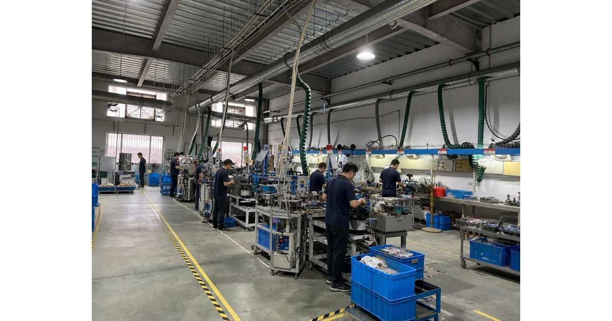
A chemical dosing skid pressure gauge is a local diagnostic instrument installed around a metering pump discharge, backpressure valve, relief line or injection point. In water and wastewater treatment it helps operators see blocked injection quills, failed check valves, air locking, crystallizing chemicals and abnormal backpressure before dosing accuracy is lost. This guide explains how to select the pressure range, wetted materials, diaphragm seal, pulsation protection and installation point without treating a chemical feed skid like an ordinary clean-water pump.
What a chemical dosing skid pressure gauge tells you
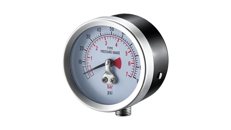
Chemical dosing skid pressure gauge selection starts with understanding the measuring point. On a metering pump skid, pressure is not only a process value; it is a troubleshooting signal. Rising discharge pressure can indicate a blocked injection quill, closed isolation valve, crystallized chemical or plugged check valve. Low or unstable pressure can point to air binding, a damaged pump diaphragm, empty day tank or failed backpressure valve.
Operator training material from the Pennsylvania Department of Environmental Protection describes common chemical feed accessories such as calibration chambers, pressure relief valves and backpressure valves. See the PA DEP chemical feed training module for this system context. A pressure gauge is useful only when it is installed where these components affect the reading.
For water treatment, cooling towers, pH adjustment, hypochlorite dosing, coagulant dosing and wastewater odor control, specify the gauge after defining chemical, concentration, normal discharge pressure, maximum pump pressure, relief valve setting and injection point backpressure.
Compare Chemical-Resistant Gauge OptionsReview stainless steel, diaphragm seal and corrosion-resistant choices→Choose the pressure range from pump and relief conditions
The best range is not simply the highest pressure printed on the pump datasheet. Start with normal discharge pressure, expected backpressure, maximum pump capacity, relief valve setting and any hydrostatic test or blocked-line scenario. Normal operating pressure should sit in a readable part of the dial, while the upper range must tolerate the credible abnormal pressure before the relief device opens.
| Condition | Gauge selection question | Why it matters |
|---|---|---|
| Normal dosing | Where does pressure sit during stable feed? | Keeps the needle readable for daily checks. |
| Blocked injection point | What pressure appears before relief opens? | Prevents gauge overload during a common failure mode. |
| Backpressure valve | Is the gauge upstream or downstream of the valve? | The same skid can show different pressure at different points. |
| Pulsating metering pump | Is a snubber, dampener or remote mount needed? | Reduces pointer flutter and movement wear. |
If the system can see sharp pulsation, review the pressure gauge snubber and pulsation protection guide instead of masking the issue with an unreadably high range.
Wetted materials and diaphragm seals for chemical feed service
Chemical compatibility is the second filter. Dilute sodium hypochlorite, ferric chloride, alum, caustic soda, sulfuric acid, antiscalant and polymer solution do not behave the same way. Confirm the wetted socket, Bourdon tube, diaphragm, gasket and fill fluid with the chemical concentration and temperature. Do not infer compatibility from stainless steel alone.
A diaphragm seal or isolating diaphragm gauge may be needed when the medium is corrosive, crystallizing, viscous, dirty or unsafe to enter a Bourdon tube. The seal separates the process chemical from the pressure element, but it also adds response limits, fill-fluid considerations and cleaning requirements. For product families, compare isolating diaphragm gauge options and stainless steel pressure gauges.
For food, potable water or high-purity chemical dosing, ask the project engineer whether material certificates, cleaning method, elastomer grade or a named standard is required. Those requirements must be confirmed by the manufacturer; they should not be invented from a catalog photo.
Send Dosing Skid Pressure DataInclude chemical, concentration, pump pressure and relief setting→Installation points on a dosing skid change the diagnosis
One chemical dosing skid may need more than one pressure point. A gauge immediately after the pump tells you pump discharge behavior. A gauge before a filter or injection quill helps diagnose plugging. A gauge across a filter or strainer can show maintenance demand. A gauge downstream of a backpressure valve may not show pump stress clearly.
Keep the gauge visible from the operating side, isolated by a clean compatible valve, and protected from chemical spray. Avoid low pockets where crystals or sludge settle into the socket. For outdoor skids, confirm case material, ingress protection, sun exposure and winterization. For vibrating pump frames, a short remote line or damped arrangement can be more reliable than a gauge mounted directly on a vibrating discharge fitting.
Thread choice and sealing practice are also part of the selection. If the skid uses NPT, BSP, G or metric threads, specify the exact connection and orientation. The pressure gauge thread connection guide explains why thread families should not be mixed on chemical service piping.
What the gauge cannot prove by itself
A local gauge cannot prove dosing accuracy, chemical concentration, pump stroke calibration, residual chlorine, pH endpoint or regulatory compliance. It also cannot prove that the relief valve is sized correctly or that the injection point will remain clean. Treat the gauge as one diagnostic layer within the chemical feed system.
Do not rely on a steady pressure reading alone. Pair it with calibration column tests, pump stroke settings, chemical consumption records, flow signal, residual analyzer data and routine inspection of check valves and injection quills. A stable but wrong backpressure can still produce underfeed or overfeed if the pump, valve or injection point is misapplied.
For hazardous chemicals, high concentration acids, sodium hypochlorite decomposition risk, confined chemical rooms or pressure above the skid supplier limit, final selection should be checked by the responsible process or safety engineer.
RFQ checklist for chemical dosing skid pressure gauge selection
A useful RFQ for chemical dosing skid pressure gauge selection should include the chemical name, concentration, temperature, normal discharge pressure, maximum pump pressure, relief valve setting, injection point pressure, pulsation severity, desired dial size, connection thread, installation orientation, wetted materials, seal requirement and certificate requirement.
- State whether the gauge is for hypochlorite, coagulant, caustic, acid, antiscalant, polymer or another reagent.
- Confirm whether the gauge sees clean liquid, crystals, sludge, gas pockets or periodic flushing.
- Specify if a diaphragm seal, snubber, pressure dampener, remote mount or isolation valve is expected.
- Provide any site rules for potable water contact, corrosion resistance, documentation or maintenance access.
With these details, a supplier can recommend a readable, chemically compatible and maintainable pressure gauge instead of guessing from pump size alone.
For 304 or 316L stainless steel gauges rated for chemical dosing media, review Manogauge's stainless steel pressure gauge manufacturer page.
Dosing pressure must be read at the point that explains the pump's work. A gauge at the pump discharge can show backpressure, while a gauge after an injection quill may also include check-valve, mixer or line losses. Mark the location and isolation state in the P&ID. Compare the reading with pump speed, stroke setting and relief-valve status; a low reading can result from an empty chemical tank or failed check valve, not only from low pump output.
Compatibility requires the chemical name, concentration, temperature and cleaning method. Confirm diaphragm, socket, seals, capillary fill and connection materials as a set. Small passages can crystallise or plug, and pulsation can fatigue a pointer; a flush diaphragm, suitable snubber or remote mounting may help only after the maintenance method is defined. Never infer suitability from the case material alone.
A chemical dosing skid pressure gauge selection RFQ should include pump shutoff pressure, relief setting, normal flow, medium, temperature, connection, range, accuracy, pulsation, hazardous-area requirements and cleaning access. The chemical supplier and instrument manufacturer should confirm the final wetted configuration.
Include operating modes in the selection review. A dosing pump may see dead-head pressure during a closed injection valve, but only line pressure during normal flow. The gauge range must cover both without making the normal indication unreadably small. Check whether the relief valve returns chemical to the tank and whether the gauge is isolated during flushing. These details often explain a high or low reading more reliably than changing the gauge.
During commissioning, verify zero, response and leakage with the approved chemical or a compatible test medium. Record the baseline at normal stroke rate and again after the skid reaches temperature. Never use an unverified gauge indication to override a relief or interlock setting.
Include operating modes in the selection review. A dosing pump may see dead-head pressure during a closed injection valve, but only line pressure during normal flow. The gauge range must cover both without making the normal indication unreadably small. Check whether the relief valve returns chemical to the tank and whether the gauge is isolated during flushing. These details often explain a high or low reading more reliably than changing the gauge.
During commissioning, verify zero, response and leakage with the approved chemical or a compatible test medium. Record the baseline at normal stroke rate and again after the skid reaches temperature. Never use an unverified gauge indication to override a relief or interlock setting.
Also confirm the gauge can be safely isolated before flushing or decontamination, and record the expected reading at minimum and maximum dosing rates for future troubleshooting.
How to turn chemical concentration, pulsation, diaphragm isolation, calibration access and leak containment into a purchase specification
A useful specification begins with the process rather than the catalogue name. Record the normal operating value, the minimum and maximum credible values, the upset condition, the medium composition, the process temperature and the way the instrument will be mounted. Then state what the operator must see: a stable local indication, a peak, a differential, a switch point or a value that will be compared with a calibrated reference. This distinction matters because a gauge can be mechanically accurate yet unsuitable when its sensing element, connection or response is wrong for the installation.
Separate the continuously expected condition from the short duration event. For chemical concentration, pulsation, diaphragm isolation, calibration access and leak containment, the short event may be more important than the average reading, but it should not be handled by quietly selecting a larger dial range. A larger range reduces readability and can increase the error at the operating point. Conversely, a range selected too tightly can expose the element to repeated overload. Document the expected cycle, the allowable overpressure and the required indication during start-up, shutdown and cleaning. If those values are unavailable, the final range must remain a site-engineering decision.
Installation details deserve the same attention as the gauge body. Confirm whether the tapping point is exposed to vibration, pulsation, water hammer, thermal shock, condensation, washdown or a corrosive atmosphere. Provide an isolation valve where safe maintenance requires it, and consider a gauge cock, siphon, snubber, diaphragm seal or remote mounting only when its effect on response and calibration is understood. The connection thread must match the mating component; NPT, BSP/G and metric threads are not interchangeable simply because their nominal size appears similar. Never force a mismatched thread or use sealant to compensate for the wrong standard.
Before release, ask for the evidence that is actually needed for the job: dimensional drawing, wetted-material declaration, accuracy statement, calibration method, pressure test requirement and packing or cleanliness instruction. Do not request certificates as a substitute for checking the process chemistry or hazard classification. Standards and customer specifications may define construction, testing or documentation, but they do not automatically prove compatibility with every concentration, temperature or cleaning cycle. The responsible engineer should reconcile the instrument data sheet with the P&ID, valve arrangement and maintenance procedure.
Commissioning should establish a baseline. With the process in a known condition, record the gauge indication, reference reading, temperature, pump or compressor state and any pointer oscillation. Recheck after the system reaches normal load and after a controlled shutdown. A drifting zero, a slow response, a blocked impulse path or an unexpectedly quiet pointer can all be failure signals rather than evidence of good performance. Trend records also make later replacement decisions more reliable because the next instrument can be specified from observed service instead of a generic catalogue assumption.
The practical conclusion for chemical concentration, pulsation, diaphragm isolation, calibration access and leak containment is to select the complete measurement chain: sensing element, wetted material, range, accuracy, connection, mounting, protection accessory and documentation. The product photograph on this page identifies the real Manogauge gauge construction used as a reference; it is not proof that the same configuration is correct for every medium or pressure. Confirm the final model, dimensions and available options against the current data sheet before purchase.
Key takeaways
- A dosing skid gauge is a diagnostic instrument, not proof of dosing accuracy by itself.
- Select range from normal pressure, blocked-line pressure and relief valve setting.
- Chemical compatibility must include socket, Bourdon tube, diaphragm, gasket and fill fluid.
- Gauge location relative to the pump, backpressure valve and injection point changes the meaning of the reading.
Related buyer pages
Diaphragm pressure gauge manufacturerProtect gauges from corrosive dosing chemicals, crystallizing media and metering pump pulsation.
Stainless steel pressure gauge manufacturer316L wetted parts and corrosion-service RFQs for chemical skids.
Related reading
- 316L Stainless vs Brass Pressure Gauges: Corrosion Guide
316L vs brass pressure gauge wetted parts compared for corrosion risk in water, steam, ammonia, seawater, chlorides, CIP/SIP cleaning and diaphragm seals.
- A2L R-454B Refrigerant Pressure Gauge Selection
A2L R-454B refrigerant pressure gauge selection for HVAC service: manifold gauge use, PT chart checks, service ports, gauge range and safe workflow.
- Ammonia Refrigeration Pressure Gauge: R717 Materials and Safety
Ammonia refrigeration pressure gauge guide for R717 cold storage: suction, discharge, oil, defrost ranges, material compatibility and safety checks.
- Nitrogen Blanketing Pressure Gauge Selection
Nitrogen blanketing pressure gauge selection for low-pressure storage tanks: range, capsule gauges, regulators, vents, oxygen-deficiency risk and RFQ checks.
- CO2 Transcritical Pressure Gauge Selection
CO2 transcritical refrigeration pressure gauge selection for R744 racks: high-side pressure, flash tank and suction points, materials and safety cases.
Frequently asked questions
Where should a chemical dosing skid pressure gauge be installed?
Install it at the pressure point you need to diagnose: immediately after the metering pump for discharge behavior, before the injection quill for plugging, near a filter for maintenance, or around the backpressure valve when valve performance is the concern.
Do chemical dosing pumps need a snubber before the pressure gauge?
Many metering pumps create pulsating discharge pressure. A snubber, dampener, remote mount or liquid-filled arrangement may be needed, but the choice must be compatible with the chemical and maintenance practice.
When is a diaphragm seal needed on a dosing skid gauge?
Use a diaphragm seal when the chemical is corrosive, crystallizing, viscous, dirty or unsafe for direct Bourdon tube contact. Confirm diaphragm material, gasket, fill fluid and temperature limits.
Can one pressure gauge confirm chemical dosing accuracy?
No. The gauge helps diagnose pressure conditions, but dosing accuracy also depends on pump calibration, stroke setting, chemical level, flow signal, check valves, injection point condition and analyzer feedback.
What information should be included in an RFQ?
Include chemical name and concentration, temperature, normal and maximum pressure, relief valve setting, injection point pressure, pulsation severity, connection thread, wetted materials, seal requirement and certificates.