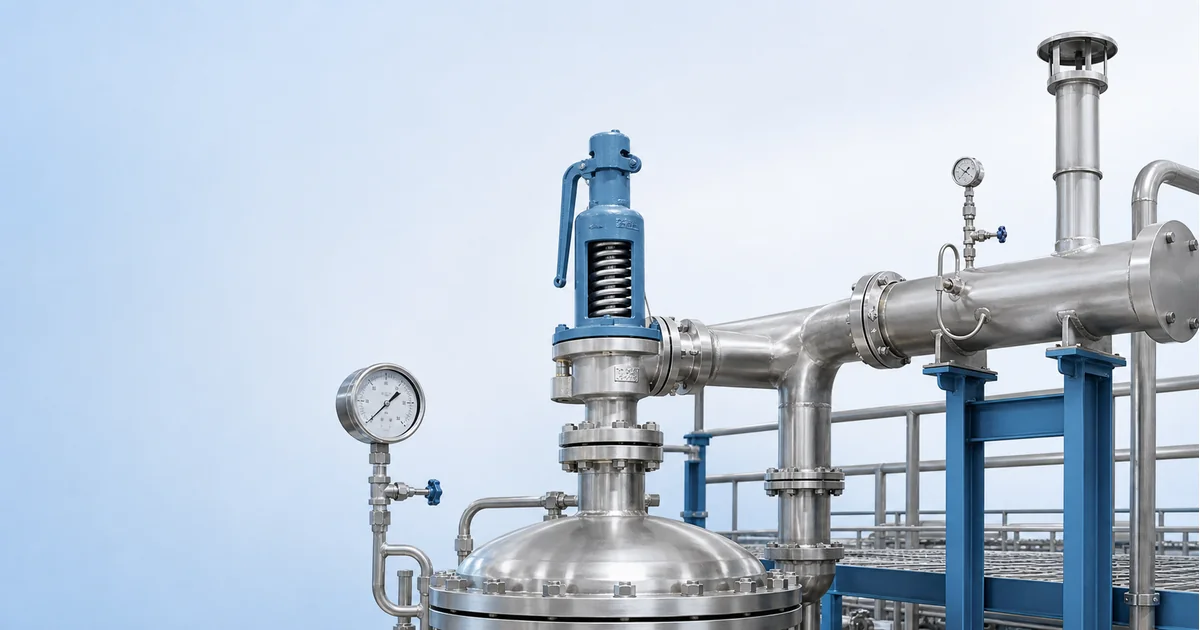
A pressure relief valve gauge is not the device that protects a vessel; the relief valve or rupture disc does that job. The gauge helps operators see whether the protected equipment is running too close to the relief set pressure, whether discharge backpressure is abnormal, and whether a rupture disc or relief path needs inspection. This guide explains how to select pressure range, mounting position, wetted materials and documentation for safety relief valve applications without implying that a gauge can replace code-compliant pressure protection.
What a pressure relief valve gauge can and cannot tell you
Pressure relief valve gauge selection starts with a boundary: the gauge is an indication and diagnostic instrument, not a protective device. A safety relief valve is intended to open when system pressure reaches its set pressure, while a rupture disc is a non-reclosing device that opens when its burst pressure is reached. A gauge near this equipment helps operators see operating pressure, pressure creep, blocked discharge symptoms or pressure trapped between devices.
OSHA pressure-vessel guidance notes that no valves or T-fittings should be placed between a vessel and its safety relief valve in ordinary arrangements. See the OSHA pressure vessel inspection guidance for the safety context. In practical terms, a gauge connection must not create a restriction, dead leg or isolation error that defeats the relief path.
Use the gauge as one layer of visibility in pressure vessels, pump skids, compressed air receivers, boiler auxiliaries, hydraulic power packs and chemical process lines. Final relief device sizing, set pressure and code compliance remain the responsibility of the vessel, piping or process engineer.
Revisar conceptos de selección de manómetros ->Compare range, accuracy, wetted materials and connection choices→Select the gauge range around operating pressure and relief set pressure
The useful pressure range depends on normal operating pressure, maximum allowable working pressure, relief valve set pressure, expected overpressure and test conditions. If the gauge range is too low, normal upset conditions can overload the movement. If the range is too high, the operator cannot see gradual creep toward the relief setting.
| Selection input | What to confirm | Gauge implication |
|---|---|---|
| Normal operating pressure | Stable pressure during expected load | Put normal reading in a readable dial zone. |
| Relief set pressure | Set pressure from approved relief documentation | Avoid a range that hides pressure creep near set point. |
| MAWP or design limit | Limit from vessel or piping documentation | Do not use gauge indication as proof of code compliance. |
| Hydrostatic or pneumatic test | Whether the gauge remains installed during test | May require a temporary higher-range test gauge. |
For dial readability and mechanical protection, compare the principles in the pressure gauge accuracy class selection guide and the pressure gauge overpressure protection guide.
Where pressure gauges belong around relief valves and rupture discs
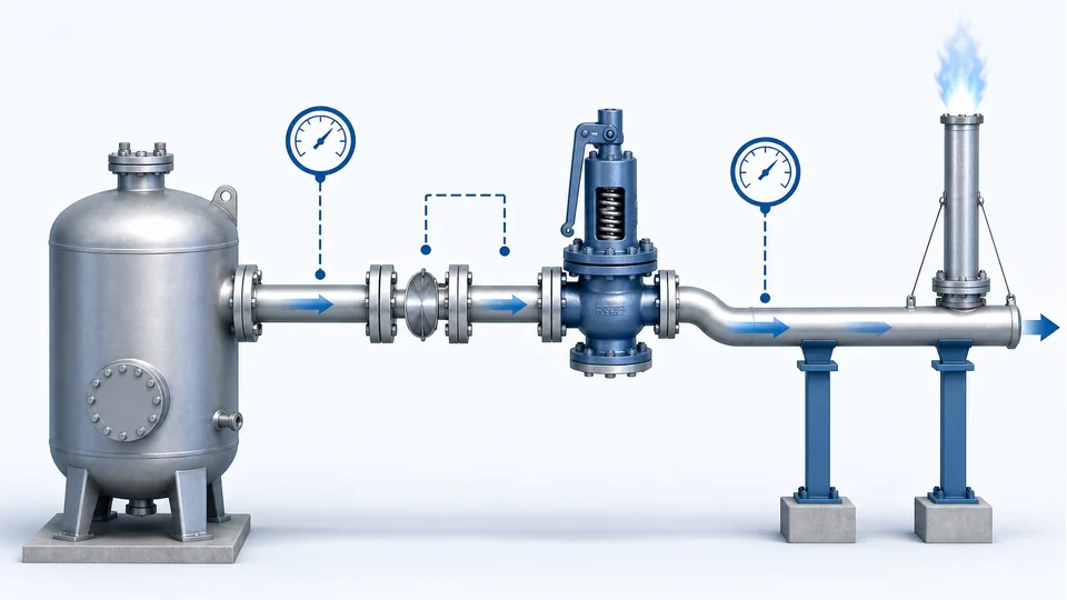
A pressure point upstream of the relief valve shows the protected equipment pressure. A pressure point downstream of the valve can indicate discharge header backpressure or a blocked vent path, but it must be designed so it does not interfere with relief capacity. When a rupture disc is installed upstream of a relief valve, an interspace pressure indication may be used to detect disc leakage or rupture, depending on the approved assembly design.
Do not add random gauge tees into a relief inlet line. Relief inlet pressure loss, outlet backpressure, pipe support, drainage, discharge direction and isolation practice are safety design topics. A small instrument branch may be acceptable only when it is part of the engineered arrangement and maintained open, clean and compatible with the process fluid.
For Manogauge product families that may be evaluated for local indication, review stainless steel pressure gauges for corrosive industrial service and isolating diaphragm gauges when the medium is dirty, corrosive or likely to plug a Bourdon tube.
Enviar datos de aplicación del manómetro ->Include medium, set pressure, MAWP, installation point and certificate needs→Backpressure, media compatibility and vibration risks

Relief valve discharge systems may see built-up backpressure during a relief event or superimposed backpressure from a common header. A downstream gauge can help maintenance teams see abnormal header pressure, but the reading does not prove that the relief valve is correctly sized or that all dynamic effects are acceptable. For balanced bellows, pilot-operated or conventional valves, backpressure sensitivity must be checked against the valve documentation.
Media compatibility matters as much as pressure. Steam service may require a siphon or cooling leg before a gauge. Corrosive chemicals may require 316L wetted parts or a diaphragm seal. Oxygen service needs cleaned, compatible materials and strict contamination control. Dirty or polymerizing service can plug a small gauge connection and give a falsely calm reading.
Vibration from compressors, pumps and relief discharge events can damage movements and pointer stops. If vibration is expected, consider liquid filling, remote mounting, a snubber where appropriate, or a protected instrument line. The choice must not compromise relief response or create maintenance traps.
What the gauge cannot prove during a relief event
A local gauge cannot prove relief valve capacity, certified set pressure, blowdown, reseating performance, rupture disc burst tolerance, discharge reaction force or regulatory compliance. It also cannot prove that a blocked outlet, closed isolation valve or corroded vent stack will be found before demand. These items require engineering calculation, inspection, certified testing and site procedures.
During a fast relief event, a mechanical gauge may lag, oscillate or be unreadable. Treat it as post-event evidence and routine operating visibility, not as the primary safety instrumented function. For hazardous fluids, high pressure gas, toxic discharge, steam, oxygen or explosive atmosphere service, final gauge selection should be reviewed with the responsible safety engineer and the relief device supplier.
Manogauge can support local indication choices, but the application data must come from the project: fluid, temperature, normal pressure, set pressure, MAWP, connection standard, discharge system, cleaning requirement and documentation level.
RFQ checklist for pressure relief valve gauge selection
A useful RFQ for pressure relief valve gauge selection should include the protected equipment type, process medium, normal pressure, relief set pressure, maximum expected pressure, temperature, installation point, connection thread or flange, wetted material, case material, ingress protection, vibration exposure and certificate needs.
- State whether the gauge is upstream of the relief valve, downstream on the discharge header or between a rupture disc and relief valve.
- Confirm whether the service is steam, compressed air, hydraulic oil, oxygen, corrosive liquid, gas, slurry or polymerizing medium.
- Provide any site restrictions on isolation valves, test ports, cleaning, pressure testing and maintenance access.
- Ask whether a siphon, diaphragm seal, restrictor, remote mounting line or liquid-filled case is allowed by the engineered design.
With these inputs, a supplier can recommend a readable and maintainable pressure gauge while keeping the relief path and code responsibility clearly separated.
Key takeaways
- A pressure relief valve gauge is diagnostic indication, not the protective device.
- Select range from normal pressure, relief set pressure, MAWP and test conditions.
- Gauge connections must not restrict, isolate or weaken the relief path.
- Downstream and rupture-disc interspace readings can help maintenance, but they do not prove relief capacity.
Часто задаваемые вопросы
Can a pressure gauge replace a pressure relief valve?
No. A pressure gauge only indicates pressure. Overpressure protection requires a correctly selected and maintained relief valve, rupture disc or other approved protective device.
Where should a gauge be installed near a safety relief valve?
Common useful points are on the protected equipment, on an engineered downstream discharge header point, or between a rupture disc and relief valve when that assembly requires leak detection. Do not add a tee that restricts the relief inlet.
Should the gauge range equal the relief valve set pressure?
Not automatically. The range should make normal pressure readable while tolerating credible abnormal pressure, test conditions and the approved set pressure margin.
What does pressure between a rupture disc and relief valve mean?
Interspace pressure may indicate rupture disc leakage, disc failure, thermal expansion or blocked venting, depending on the assembly. The interpretation must follow the engineered design and maintenance procedure.
Can a downstream gauge prove that relief capacity is adequate?
No. Downstream pressure indication can reveal abnormal backpressure, but relief capacity, reaction forces and code compliance require calculation, certified valve data and inspection.