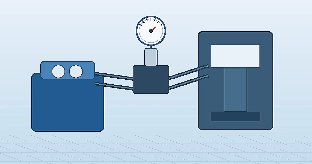
Hydraulic pressure gauge selection is the process of matching a gauge to a hydraulic circuit's pressure range, pulsation, vibration, fluid, connection and maintenance task. In presses, power units, mobile machinery and test benches, a gauge is often the fastest local clue to pump output, valve setting, filter loading or actuator resistance. The reading is useful only when the gauge is ranged, protected and installed for the actual circuit.
Why hydraulic pressure gauge selection is different
Hydraulic pressure gauge selection is different from water, air or low-pressure utility service because hydraulic circuits combine high static pressure with sharp pressure spikes, pump ripple, valve shock and machine vibration. A press, injection moulding machine, hydraulic power unit or mobile excavator may run at a stable set pressure for minutes, then see a short surge during clamping, reversal or relief-valve operation.
ISO describes ISO 4413:2010 as the international standard for general rules and safety requirements for hydraulic fluid power systems and components on machinery. A pressure gauge is only one component in that safety context, but the same logic applies: the instrument must suit the intended pressure, hazards, maintenance access and reliable operation requirements. For related instrument basics, compare dry vs liquid-filled pressure gauges and the pressure gauge snubber selection guide.
Browse Hydraulic Pressure Gauge Options →Explore 143+ industrial gauge models→Place hydraulic system pressure gauges at decision points
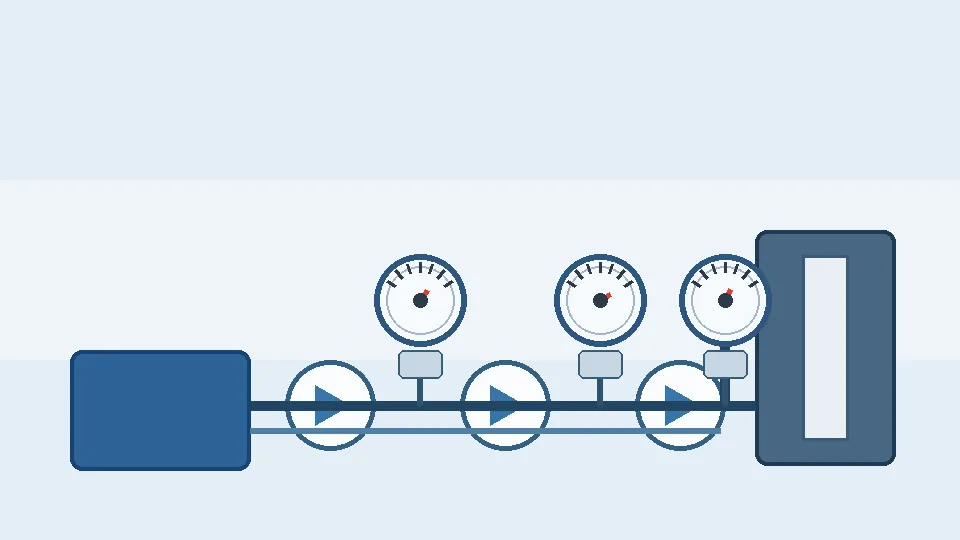
A useful hydraulic system pressure gauge is placed where the reading supports a real decision. Common points include pump outlet pressure, pressure-reducing valve outlet, accumulator charging line, filter differential pressure, manifold test port and actuator work line. A gauge located far downstream of a valve may be easy to see but poor for diagnosing pump output. A gauge installed directly on a vibrating pump body may fail early even if the range is correct.
| Measurement point | What the reading helps judge | Typical gauge choice |
|---|---|---|
| Pump outlet or main pressure line | Pump output, relief setting, pressure spikes, system baseline | Liquid-filled Bourdon gauge, snubber if pulsation is severe |
| Manifold test port | Valve setting, local troubleshooting, commissioning | Compact hydraulic gauge with matching test coupling |
| Accumulator line | Charge/discharge behavior and isolation checks | Gauge rated above maximum system pressure with isolation valve |
| Filter inlet/outlet | Element loading and bypass risk | Differential pressure gauge or paired local gauges |
Choose range for normal pressure, relief pressure and spikes
Correct range selection for a hydraulic pressure gauge starts with three numbers: normal working pressure, relief-valve setting and the highest spike the system generates. A common engineering rule is to keep normal working pressure in the middle third of the dial (25–75% of full scale) so the Bourdon tube operates within its elastic region and pointer accuracy stays within specification. A gauge installed at 90% of its range during normal operation will drift, fatigue and fail faster than one operating in its linear zone.
The relief-valve setting typically sits 10–20% above normal working pressure. Select a gauge whose full-scale range clears the relief setting with margin. For example, a 210 bar working pressure system with a 230 bar relief setting suits a 400 bar full-scale gauge, keeping normal pressure at 52% and relief pressure at 57% of span — both comfortably within the middle zone.
Pressure spikes during clamping, valve shock and end-of-stroke events can be two to five times normal pressure and last only milliseconds. A snubber or restrictor damps these spikes from the Bourdon tube, but the gauge range must still accommodate any spike the snubber allows through. If spikes are severe and a snubber is not fitted, size the range to the spike maximum and accept reduced readability at normal pressure, or use a digital gauge with peak-hold to capture spike values without over-ranging a Bourdon instrument.
| System characteristic | Range selection guidance |
|---|---|
| Normal working pressure well below relief | Size to 2× normal pressure; keeps normal reading at ~50% FS |
| Normal pressure close to relief setting | Size so relief pressure ≤ 75% FS; accept lower normal-pressure resolution |
| Severe spike events (valve slam, press reversal) | Add snubber and size to spike maximum, or use digital gauge with peak-hold |
| Variable duty cycle (low idle + high load) | Consider two gauges at different ports or a dual-scale dial |
Accuracy class requirements for hydraulic gauge specifications

Accuracy class is stated as a percentage of full-scale span, not of the live reading. A hydraulic gauge on a 400 bar range at EN 837-1 class 1.6 carries ±6.4 bar uncertainty across the entire scale. For a circuit operating normally at 250 bar — two-thirds of full scale — that same ±6.4 bar represents ±2.6% of the working reading. Selecting a tighter range where the working point sits closer to mid-scale improves effective measurement quality without changing the accuracy class.
| EN 837-1 class | ASME B40.100 grade | Accuracy band | Hydraulic application |
|---|---|---|---|
| 0.6 | Grade 2A | ±0.6% FS | Hydraulic test stands, servo-controlled cylinders |
| 1.0 | Grade 1A | ±1.0% FS | Precision press force monitoring, acceptance testing |
| 1.6 | Grade B | ±1.6% FS | General hydraulic circuits — the standard choice |
| 2.5 | Grade C | ±2.5% FS | Rough indication only; not recommended for hydraulic decision points |
Class 1.6 covers most hydraulic applications. It is sufficient for confirming system pressure against relief valve settings, monitoring pump outlet pressure and checking filter differential pressure. Move to class 1.0 when press tonnage tolerance, servo position repeatability or acceptance-test records require tighter numbers.
Vibration reduces effective accuracy faster than the nameplate implies. A class 1.6 gauge on a high-cycle hydraulic power unit degrades through pointer-mechanism wear and Bourdon tube fatigue. Liquid-filled housings and snubbers — addressed in the next section — protect the mechanism and preserve the rated accuracy over service life. Specifying a higher class without controlling vibration delivers little practical benefit.
Mark the class in your RFQ. EN 837-1 gauges show the class number on the dial face (e.g. “1.6”); ASME B40.100 gauges show the letter grade (e.g. “Grade B”). Write the class explicitly in purchase specifications — “standard accuracy” is not a specification that survives a substitution audit or pre-shipment inspection. For deeper reference on ASME vs EN accuracy grade mapping, see the EN 837-1 pressure gauge standard guide.
Liquid-filled gauges, snubbers and stainless wetted parts
Three design choices together determine whether a hydraulic pressure gauge survives its service life: fill fluid, pulsation damping and wetted-parts material.
Liquid fill. Glycerin (glycerol) is the standard fill fluid for hydraulic gauges operating between −5 °C and +65 °C. It damps pointer flutter caused by pump ripple, reduces friction on the Bourdon tube pivot bearings, and delays fatigue cracking by cushioning shock. For temperatures below −5 °C, a silicone oil fill (typically dimethylpolysiloxane) retains mobility where glycerin would become viscous. For food-grade and pharmaceutical-adjacent hydraulics, NSF H1 or FDA-compliant food-grade fill is specified. Never use glycerin where the fluid may contact water-glycol hydraulic fluid — glycerin can absorb water and dilute the system.
Snubbers. A pulsation snubber installs between the hydraulic port and the gauge inlet to restrict the rate at which pressure can rise inside the Bourdon tube. Sintered (porous-plug) snubbers provide consistent resistance and are less prone to fouling than orifice-disc types in clean hydraulic oil service. Adjustable orifice snubbers allow the restriction to be matched to the pulsation frequency. Snubber restriction must not be so high that it filters out a genuine pressure event that an operator needs to see.
Wetted-parts material. Standard hydraulic gauges use steel or brass Bourdon tubes. For water-glycol hydraulic fluids, phosphate ester fluids or any moisture-contaminated system, specify 316L stainless steel wetted parts. Brass is attacked by water-based hydraulic fluids and will fail prematurely. Where the hydraulic medium is a specialty fluid (bio-hydraulic oil, polyglycol), verify chemical compatibility of all elastomers and metals against the fluid's safety data sheet before specifying a standard gauge.
Installation details for presses, power units and manifolds
Mounting location, process connection and isolation determine long-term gauge reliability as much as gauge specification does.
Isolation valve. Always fit an isolation valve (needle valve or block-and-bleed valve) between the pressure port and the gauge. Without isolation, replacing a failed gauge on a live hydraulic circuit requires depressurising the entire system. A simple needle valve allows the gauge to be isolated, removed and replaced while the system remains pressurised. Specify a valve with a rated working pressure at least equal to the system relief setting.
Process connection torque. Hydraulic gauge connections (typically 1/4 BSP, 1/4 NPT or 1/4 SAE straight thread) must be torqued to fitting-manufacturer specifications, not hand-tightened. Under-torquing causes leaks; over-torquing can crack the gauge socket or distort the Bourdon tube anchor, introducing a zero error. Use a crow-foot or open-end spanner — never apply torque to the gauge case or window.
Orientation. Liquid-filled gauges should be mounted with the dial face vertical (12 o'clock stem up or angled, not lying flat). Horizontal stem mounting is acceptable for manifold or back-mounted gauges, but filling the case partially with glycerin on a flat-mounted gauge creates an air pocket that reduces damping effectiveness. If a flat-mount position is unavoidable, bleed the gauge case during installation to remove trapped air.
Vibration isolation. On pump bodies or vibrating structures, soft-mount the gauge with a stainless braided hose flexible connector between the rigid port and the gauge. The hose absorbs vibration that would otherwise fatigue the Bourdon tube and loosen the case. Specify hose rated above system working pressure with a burst pressure well above the relief setting.
Accessibility. Place gauges where an operator can read them without obstruction from machine guards or hydraulic cylinders. A gauge that cannot be read without opening a guard will not be read during operation, defeating its purpose. Mark normal operating pressure and maximum allowable pressure on the dial bezel with a permanent marker or adhesive arc label.
Risk boundaries: what a hydraulic gauge cannot prove
A hydraulic pressure gauge does not prove flow rate, oil cleanliness, actuator force, accumulator precharge or valve condition by itself. It cannot show a millisecond pressure spike if the gauge movement and snubber are too slow. It also cannot make an underspecified hose, fitting or manifold safe. A normal pressure reading can still hide low flow, aerated oil, thermal drift, internal leakage or a blocked return path.
For presses, lifting equipment, hazardous motion, high pressure above common catalogue ranges, fire-resistant fluids, oxygen-adjacent systems or explosion-risk areas, treat this guide as a selection aid only. Confirm pressure rating, burst protection, material compatibility, standards, guarding and test procedures with the machine builder and site engineer before ordering. Manogauge can support pressure gauge selection from Zhejiang manufacturing resources, but final suitability belongs to the project specification.
Hydraulic pressure gauge selection checklist
Use this checklist to confirm specification before ordering a replacement or new hydraulic pressure gauge. A gauge that fails three or more of these checks will likely fail early or give misleading readings.
| Check | Requirement | Notes |
|---|---|---|
| Normal working pressure in range? | 25–75% of gauge full scale | Prevents fatigue and over-range failure |
| Relief setting within range? | ≤ 75% of full scale | Allows safe exposure without overpressure |
| Spike protection? | Snubber fitted or range covers spike | Unprotected spikes are the main cause of early failure |
| Fill fluid compatible? | Glycerin, silicone or food-grade as required | Verify against temperature range and fluid type |
| Wetted material compatible? | Steel for oil; SS316L for water-based fluids | Brass corrodes in water-glycol |
| Isolation valve fitted? | Yes — always | Required for safe replacement under pressure |
| Connection thread matches? | Same standard (BSP/NPT/SAE) and size | Never force unlike threads |
| Accuracy class sufficient? | ≥ 1.6% FS for monitoring; ≥ 1.0% for control loops | Use tighter class only if process requires it |
| Dial legible from operating position? | Yes | 100 mm dial minimum for distances > 2 m |
| Spare gauge available? | Yes — at least 1 | Critical circuits need a local spare |
Hydraulic gauge failure modes and replacement triggers
Knowing what hydraulic pressure gauge failures look like helps maintenance teams replace instruments before a misleading reading causes a process fault or a safety incident.
Pointer frozen or sluggish. A pointer that does not return to zero when pressure is released, or moves slowly during rapid pressure changes, usually indicates a blocked snubber orifice. Remove and clean or replace the snubber before condemning the gauge. If the snubber is clear, the Bourdon tube may be internally fouled or the pivot is worn.
Permanent zero offset. If the pointer rests above zero with no system pressure, the Bourdon tube has been overpressurised and taken a set beyond its elastic limit. The gauge is unserviceable: its indicated reading is now wrong by the zero offset at every point in the range. Replace immediately and identify the root cause of the overpressure event.
Fogged or discoloured lens. Glycerin expands with heat and, if the gauge is sealed, may leak through the case back seal or around the fill plug. A fogged lens typically means the fill fluid has emulsified with water contamination or has begun to deteriorate. A milky appearance inside the case is a sign of water ingress — replace the gauge and investigate whether the hydraulic fluid itself is contaminated.
Glycerin leak. Liquid-filled gauges with a leak at the process connection or case back lose their damping protection and will fail from vibration fatigue at an accelerated rate. A small external glycerin stain is a warning; a gauge that has lost most of its fill should be replaced, not topped up in the field.
Cracked or shattered window. Inspect after any overpressure event. A cracked window is a hazard if the Bourdon tube fails — replace the gauge if the window is not intact.
Set a planned replacement interval based on duty severity: two to three years for normal industrial duty, annually for severe pulsation or high-cycle press applications, and on-condition for accessible critical monitoring points.
Specifying hydraulic gauges for procurement and maintenance planning
A clear purchase specification reduces error rate when ordering replacement gauges and helps stockroom staff confirm a stored spare matches what is installed.
Minimum specification line items. A complete hydraulic gauge specification states: pressure range (e.g. 0–400 bar), dial size (63 mm, 100 mm or other), process connection thread type and size (e.g. 1/4 BSP male, centre-back), accuracy class (e.g. ±1.6% FS to EN 837), case material (steel, stainless steel or brass), fill type (glycerin-filled or dry), wetted-parts material (steel, 316L SS or brass) and any certification requirement (SIL, ATEX, PED).
Interchangeability documentation. When a gauge is installed on a machine, tag it with the full specification and stock code. Photograph the nameplate and store the image in the maintenance management system. A photograph prevents the common error of replacing a 400 bar gauge with a 250 bar gauge of the same physical size.
Stocking strategy. For hydraulic circuits with four or more gauges of the same specification, holding two spare gauges locally is justified. For single-unit special specifications (e.g. food-grade fill, stainless case), hold one spare and know the lead time from supplier. A gauge failure on a critical press that causes production downtime for 48 hours while a replacement is sourced is far more expensive than the cost of a spare.
Calibration and traceability. Hydraulic system gauges used only for operational monitoring (not safety or SIL) do not normally require formal calibration records. Gauges used to set relief valves, verify proof-test pressures or support regulatory inspection should have a calibration certificate traceable to national measurement standards. Specify this requirement at purchase — a gauge supplied with a certificate of conformance (CoC) and one with a UKAS/DAkkS calibration certificate are not the same document.
Related products
- Liquid-Filled Pressure Gauge - Radial (ZX-06-R) — 0–60 MPa
- Shock-Resistant Pressure Gauge - Radial (ZX-03-R) — 0–270 psi
- Stainless Steel Pressure Gauge - Radial (ZX-01-R) — 0–100 MPa
Frequently asked questions
What pressure range should a hydraulic pressure gauge use?
Start from normal working pressure, relief-valve setting and possible pressure spikes. Keep normal pressure in the readable middle of the dial while leaving enough margin for surge and OEM safety limits.
Are liquid-filled gauges better for hydraulic systems?
Usually yes when vibration or pump pulsation is present. Liquid fill damps pointer flutter and movement wear, but temperature, fill fluid and response speed still need confirmation.
When does a hydraulic gauge need a snubber?
Use a snubber or restrictor when pump ripple or valve shock causes pointer flutter or early failure. Avoid excessive restriction when fast pressure events must be visible.
Can a pressure gauge prove hydraulic flow?
No. Pressure helps diagnose circuit condition, but flow requires a flow meter or machine data. Normal pressure can still hide leakage, low flow or a blocked return path.
Which connection is common for hydraulic pressure gauges?
NPT, BSP, G and metric threads are all used. Match the actual port or test coupling before installation and never force unlike thread forms.
How often should hydraulic pressure gauges be replaced?
Replace on condition, not on a fixed calendar. In severe pulsation or high-cycle press service, inspect annually and replace every two to three years. In light-duty circuits, gauges can last five or more years. Always replace immediately after confirmed overpressure or if the pointer shows a zero offset.
Can I use a standard dry gauge on a hydraulic system?
A dry gauge can work short-term, but it will fail faster than a liquid-filled gauge on any system with pump ripple or valve shock. The lack of damping fluid accelerates Bourdon tube fatigue and bearing wear. Use a liquid-filled gauge for any hydraulic application where vibration or pulsation is present.
What fill fluid should I specify for a high-pressure hydraulic gauge?
Glycerin is standard for mineral-oil hydraulics from −5 °C to +65 °C. For cold environments, specify silicone oil fill. For water-glycol or phosphate ester hydraulic fluids, use a silicone-filled stainless steel gauge — glycerin is incompatible with water-based fluids and can dilute them if a leak occurs.
Do hydraulic pressure gauges need a calibration certificate?
Operational monitoring gauges (reading circuit pressure for operator information) do not normally require formal calibration. Gauges used to set safety relief valves, verify proof-test pressures or meet regulatory inspection requirements should have a calibration certificate traceable to national standards. Specify this at purchase if needed.
Why is glycerin fill standard on hydraulic system pressure gauges?
Hydraulic systems generate significant pulsation and vibration from pumps, motors and valve switching. Glycerin fill dampens pointer oscillation, extends Bourdon tube fatigue life, and prevents pointer pivot wear. Dry gauges on hydraulic systems typically fail within weeks from pulsation-induced metal fatigue. Specify glycerin fill as a minimum; for high-cycle systems or where ambient temperature exceeds 60°C, specify silicone fill.
What SAE or BSP port size is standard for hydraulic pressure gauge connections?
The most common hydraulic gauge port threads are: SAE 7/16-20 UNF (SAE J514, common in mobile and North American hydraulics), 1/4 BSP (G 1/4, common in European industrial hydraulics), and 1/4 NPT (US pipeline standard). SAE straight-thread ports with an O-ring face seal (ORFS) are leak-tight without thread sealant. For manifold-mounted gauges, confirm port thread type and torque specification before ordering — thread mismatch is a common hydraulic gauge installation error.