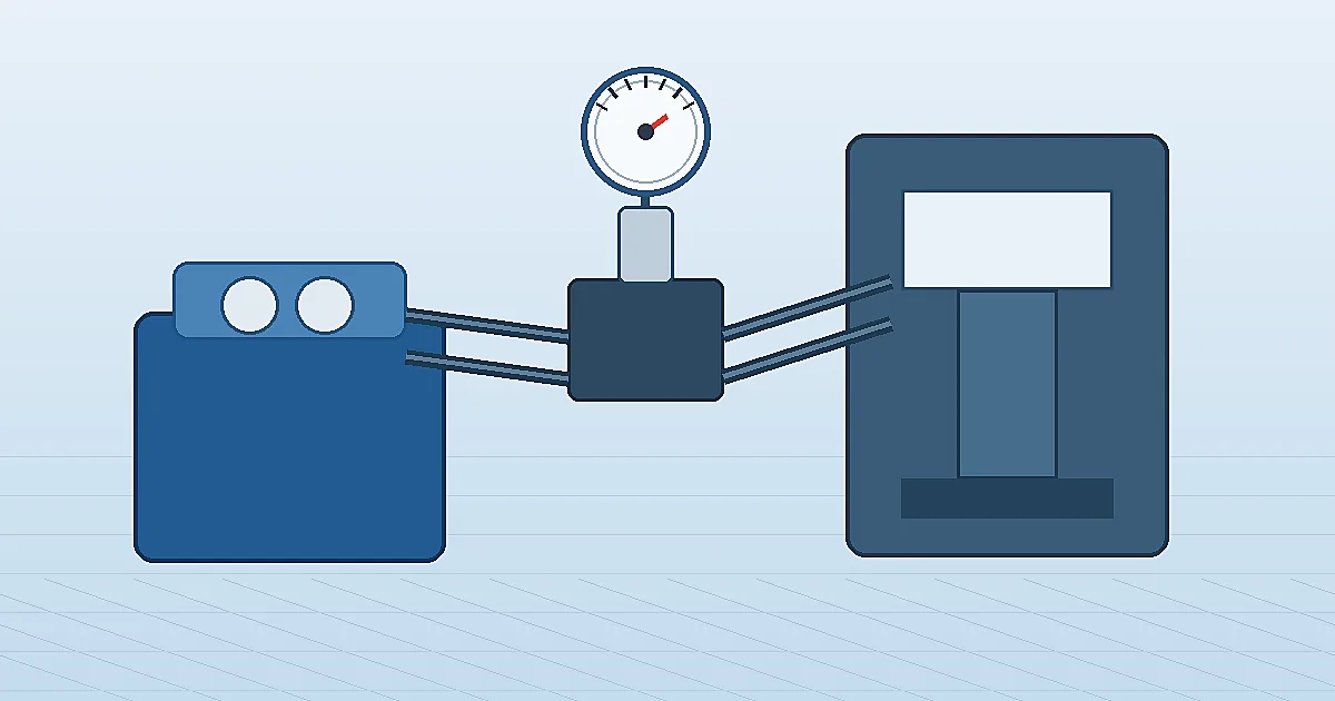
液压系统压力表选型,是根据液压回路的压力范围、脉动、振动、油液、连接方式和维护任务来匹配压力表的过程。在压力机、液压站、工程机械和测试台中,压力表常常是判断泵输出、阀门设定、过滤器负载和执行元件阻力的最快现场信号。只有量程、防护和安装方式符合真实回路,读数才有诊断价值。
为什么液压系统压力表选型更特殊
液压系统压力表选型不同于水、空气或低压公用工程,因为液压回路同时存在较高静压、瞬时压力峰值、泵脉动、阀门冲击和机械振动。压力机、注塑机、液压站或工程机械可能在设定压力下稳定运行,也可能在夹紧、换向或溢流阀动作时出现短时冲击。
ISO 将 ISO 4413:2010 定义为液压传动系统及其元件在机械设备上的通用规则和安全要求标准。压力表只是其中一个部件,但同样应符合预期压力、危险因素、维护可达性和可靠运行要求。相关基础可参考 干式与充液压力表对比 以及 压力表阻尼器选型指南。
浏览液压压力表选项 →探索143+工业压力表型号→把液压系统压力表装在能支持判断的位置
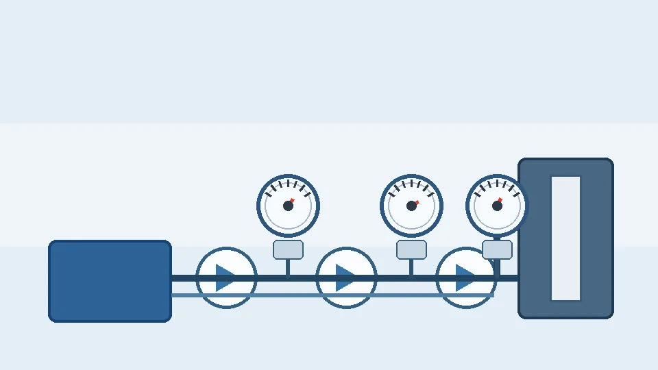
有价值的液压系统压力表,应安装在能支持实际判断的测点,例如泵出口、减压阀出口、蓄能器管路、过滤器前后、阀块测试口和执行元件工作油路。远离阀门的下游压力表可能便于观察,却不适合判断泵输出;直接装在强振动泵体上的压力表,即使量程正确也可能早期失效。
| 测点 | 读数用途 | 常用压力表 |
|---|---|---|
| 泵出口或主压力管路 | 泵输出、溢流设定、压力峰值、系统基线 | 充液布尔登管压力表,脉动严重时加阻尼器 |
| 阀块测试口 | 阀门设定、局部故障排查、调试 | 匹配测试接头的小型液压压力表 |
| 蓄能器管路 | 充放压力变化和隔离检查 | 高于系统最大压力的压力表,配隔离阀 |
| 过滤器进出口 | 滤芯堵塞和旁通风险 | 差压表或两只现场压力表 |
Choose range for normal pressure, relief pressure and spikes
Correct range selection for a hydraulic pressure gauge starts with three numbers: normal working pressure, relief-valve setting and the highest spike the system generates. A common engineering rule is to keep normal working pressure in the middle third of the dial (25–75% of full scale) so the Bourdon tube operates within its elastic region and pointer accuracy stays within specification. A gauge installed at 90% of its range during normal operation will drift, fatigue and fail faster than one operating in its linear zone.
The relief-valve setting typically sits 10–20% above normal working pressure. Select a gauge whose full-scale range clears the relief setting with margin. For example, a 210 bar working pressure system with a 230 bar relief setting suits a 400 bar full-scale gauge, keeping normal pressure at 52% and relief pressure at 57% of span — both comfortably within the middle zone.
Pressure spikes during clamping, valve shock and end-of-stroke events can be two to five times normal pressure and last only milliseconds. A snubber or restrictor damps these spikes from the Bourdon tube, but the gauge range must still accommodate any spike the snubber allows through. If spikes are severe and a snubber is not fitted, size the range to the spike maximum and accept reduced readability at normal pressure, or use a digital gauge with peak-hold to capture spike values without over-ranging a Bourdon instrument.
| System characteristic | Range selection guidance |
|---|---|
| Normal working pressure well below relief | Size to 2× normal pressure; keeps normal reading at ~50% FS |
| Normal pressure close to relief setting | Size so relief pressure ≤ 75% FS; accept lower normal-pressure resolution |
| Severe spike events (valve slam, press reversal) | Add snubber and size to spike maximum, or use digital gauge with peak-hold |
| Variable duty cycle (low idle + high load) | Consider two gauges at different ports or a dual-scale dial |
液压压力表精度等级要求

精度等级以满量程(Full Scale, FS)百分比表示,而非实际读数的百分比。一只量程400 bar、EN 837-1精度1.6级的液压压力表,整个量程内允许误差为±6.4 bar。若系统正常工作压力为250 bar(约量程的2/3),该±6.4 bar对应读数误差约±2.6%。量程选型阶段将工作点尽量靠近刻度中部,可在不改变精度等级的前提下提高实际测量质量。
| EN 837-1精度等级 | ASME B40.100等级 | 精度带 | 液压应用场景 |
|---|---|---|---|
| 0.6 | 2A级 | ±0.6% FS | 液压试验台、伺服缸精密控制 |
| 1.0 | 1A级 | ±1.0% FS | 压力机出力监测、出厂验收测试 |
| 1.6 | B级 | ±1.6% FS | 通用液压回路——标准首选 |
| 2.5 | C级 | ±2.5% FS | 仅用于粗略指示,液压关键决策点不推荐 |
大多数液压应用选1.6级已足够。确认系统压力是否达到溢流阀设定值、监测泵出口压力、检查过滤器压差,1.6级均可胜任。当压力机吸力公差、伺服定位重复性或验收记录要求更高精度时,再选用1.0级。
振动和脉动会加速精度衰减。高循环频率的液压站会因指针机构磨损和波登管疲劳导致精度下降。充液外壳和缓冲器(见下一节)能保护内部机构,维持额定精度对应年限。
在采购规格书中明确精度等级。EN 837-1仪表表盘上印有精度级数字(如“1.6”);ASME B40.100仪表使用字母等级(如“Grade B”)。规格书中需明确写明精度等级,“标准精度”不是可通过替代品审核或出货前检验的规格。
Liquid-filled gauges, snubbers and stainless wetted parts
Three design choices together determine whether a hydraulic pressure gauge survives its service life: fill fluid, pulsation damping and wetted-parts material.
Liquid fill. Glycerin (glycerol) is the standard fill fluid for hydraulic gauges operating between −5 °C and +65 °C. It damps pointer flutter caused by pump ripple, reduces friction on the Bourdon tube pivot bearings, and delays fatigue cracking by cushioning shock. For temperatures below −5 °C, a silicone oil fill (typically dimethylpolysiloxane) retains mobility where glycerin would become viscous. For food-grade and pharmaceutical-adjacent hydraulics, NSF H1 or FDA-compliant food-grade fill is specified. Never use glycerin where the fluid may contact water-glycol hydraulic fluid — glycerin can absorb water and dilute the system.
Snubbers. A pulsation snubber installs between the hydraulic port and the gauge inlet to restrict the rate at which pressure can rise inside the Bourdon tube. Sintered (porous-plug) snubbers provide consistent resistance and are less prone to fouling than orifice-disc types in clean hydraulic oil service. Adjustable orifice snubbers allow the restriction to be matched to the pulsation frequency. Snubber restriction must not be so high that it filters out a genuine pressure event that an operator needs to see.
Wetted-parts material. Standard hydraulic gauges use steel or brass Bourdon tubes. For water-glycol hydraulic fluids, phosphate ester fluids or any moisture-contaminated system, specify 316L stainless steel wetted parts. Brass is attacked by water-based hydraulic fluids and will fail prematurely. Where the hydraulic medium is a specialty fluid (bio-hydraulic oil, polyglycol), verify chemical compatibility of all elastomers and metals against the fluid's safety data sheet before specifying a standard gauge.
Installation details for presses, power units and manifolds
Mounting location, process connection and isolation determine long-term gauge reliability as much as gauge specification does.
Isolation valve. Always fit an isolation valve (needle valve or block-and-bleed valve) between the pressure port and the gauge. Without isolation, replacing a failed gauge on a live hydraulic circuit requires depressurising the entire system. A simple needle valve allows the gauge to be isolated, removed and replaced while the system remains pressurised. Specify a valve with a rated working pressure at least equal to the system relief setting.
Process connection torque. Hydraulic gauge connections (typically 1/4 BSP, 1/4 NPT or 1/4 SAE straight thread) must be torqued to fitting-manufacturer specifications, not hand-tightened. Under-torquing causes leaks; over-torquing can crack the gauge socket or distort the Bourdon tube anchor, introducing a zero error. Use a crow-foot or open-end spanner — never apply torque to the gauge case or window.
Orientation. Liquid-filled gauges should be mounted with the dial face vertical (12 o'clock stem up or angled, not lying flat). Horizontal stem mounting is acceptable for manifold or back-mounted gauges, but filling the case partially with glycerin on a flat-mounted gauge creates an air pocket that reduces damping effectiveness. If a flat-mount position is unavoidable, bleed the gauge case during installation to remove trapped air.
Vibration isolation. On pump bodies or vibrating structures, soft-mount the gauge with a stainless braided hose flexible connector between the rigid port and the gauge. The hose absorbs vibration that would otherwise fatigue the Bourdon tube and loosen the case. Specify hose rated above system working pressure with a burst pressure well above the relief setting.
Accessibility. Place gauges where an operator can read them without obstruction from machine guards or hydraulic cylinders. A gauge that cannot be read without opening a guard will not be read during operation, defeating its purpose. Mark normal operating pressure and maximum allowable pressure on the dial bezel with a permanent marker or adhesive arc label.
风险边界:液压压力表不能证明什么
液压压力表本身不能证明流量、油液清洁度、执行元件输出力、蓄能器预充压力或阀门状态。若表机芯和阻尼器响应过慢,它也无法显示毫秒级压力峰值。压力表更不能让规格不足的软管、接头或阀块变得安全。正常压力读数仍可能掩盖低流量、油液含气、热漂移、内泄漏或回油堵塞。
压力机、起升设备、危险运动、高于常规目录范围的高压、难燃液、靠近氧气的系统或防爆区域,应把本文作为选型参考,而不是最终工程结论。订货前必须由设备厂家和现场工程师确认压力等级、防爆裂防护、材料兼容、标准、护罩和测试流程。Manogauge 可基于浙江制造资源支持压力表选型,但最终适用性以项目规格为准。
Hydraulic pressure gauge selection checklist
Use this checklist to confirm specification before ordering a replacement or new hydraulic pressure gauge. A gauge that fails three or more of these checks will likely fail early or give misleading readings.
| Check | Requirement | Notes |
|---|---|---|
| Normal working pressure in range? | 25–75% of gauge full scale | Prevents fatigue and over-range failure |
| Relief setting within range? | ≤ 75% of full scale | Allows safe exposure without overpressure |
| Spike protection? | Snubber fitted or range covers spike | Unprotected spikes are the main cause of early failure |
| Fill fluid compatible? | Glycerin, silicone or food-grade as required | Verify against temperature range and fluid type |
| Wetted material compatible? | Steel for oil; SS316L for water-based fluids | Brass corrodes in water-glycol |
| Isolation valve fitted? | Yes — always | Required for safe replacement under pressure |
| Connection thread matches? | Same standard (BSP/NPT/SAE) and size | Never force unlike threads |
| Accuracy class sufficient? | ≥ 1.6% FS for monitoring; ≥ 1.0% for control loops | Use tighter class only if process requires it |
| Dial legible from operating position? | Yes | 100 mm dial minimum for distances > 2 m |
| Spare gauge available? | Yes — at least 1 | Critical circuits need a local spare |
Hydraulic gauge failure modes and replacement triggers
Knowing what hydraulic pressure gauge failures look like helps maintenance teams replace instruments before a misleading reading causes a process fault or a safety incident.
Pointer frozen or sluggish. A pointer that does not return to zero when pressure is released, or moves slowly during rapid pressure changes, usually indicates a blocked snubber orifice. Remove and clean or replace the snubber before condemning the gauge. If the snubber is clear, the Bourdon tube may be internally fouled or the pivot is worn.
Permanent zero offset. If the pointer rests above zero with no system pressure, the Bourdon tube has been overpressurised and taken a set beyond its elastic limit. The gauge is unserviceable: its indicated reading is now wrong by the zero offset at every point in the range. Replace immediately and identify the root cause of the overpressure event.
Fogged or discoloured lens. Glycerin expands with heat and, if the gauge is sealed, may leak through the case back seal or around the fill plug. A fogged lens typically means the fill fluid has emulsified with water contamination or has begun to deteriorate. A milky appearance inside the case is a sign of water ingress — replace the gauge and investigate whether the hydraulic fluid itself is contaminated.
Glycerin leak. Liquid-filled gauges with a leak at the process connection or case back lose their damping protection and will fail from vibration fatigue at an accelerated rate. A small external glycerin stain is a warning; a gauge that has lost most of its fill should be replaced, not topped up in the field.
Cracked or shattered window. Inspect after any overpressure event. A cracked window is a hazard if the Bourdon tube fails — replace the gauge if the window is not intact.
Set a planned replacement interval based on duty severity: two to three years for normal industrial duty, annually for severe pulsation or high-cycle press applications, and on-condition for accessible critical monitoring points.
Specifying hydraulic gauges for procurement and maintenance planning
A clear purchase specification reduces error rate when ordering replacement gauges and helps stockroom staff confirm a stored spare matches what is installed.
Minimum specification line items. A complete hydraulic gauge specification states: pressure range (e.g. 0–400 bar), dial size (63 mm, 100 mm or other), process connection thread type and size (e.g. 1/4 BSP male, centre-back), accuracy class (e.g. ±1.6% FS to EN 837), case material (steel, stainless steel or brass), fill type (glycerin-filled or dry), wetted-parts material (steel, 316L SS or brass) and any certification requirement (SIL, ATEX, PED).
Interchangeability documentation. When a gauge is installed on a machine, tag it with the full specification and stock code. Photograph the nameplate and store the image in the maintenance management system. A photograph prevents the common error of replacing a 400 bar gauge with a 250 bar gauge of the same physical size.
Stocking strategy. For hydraulic circuits with four or more gauges of the same specification, holding two spare gauges locally is justified. For single-unit special specifications (e.g. food-grade fill, stainless case), hold one spare and know the lead time from supplier. A gauge failure on a critical press that causes production downtime for 48 hours while a replacement is sourced is far more expensive than the cost of a spare.
Calibration and traceability. Hydraulic system gauges used only for operational monitoring (not safety or SIL) do not normally require formal calibration records. Gauges used to set relief valves, verify proof-test pressures or support regulatory inspection should have a calibration certificate traceable to national measurement standards. Specify this requirement at purchase — a gauge supplied with a certificate of conformance (CoC) and one with a UKAS/DAkkS calibration certificate are not the same document.
相关产品
- 充油压力表 - 径向 (ZX-06-R) — 0–60 MPa
- 耐震压力表 - 径向 (ZX-03-R) — 0–270 psi
- 不锈钢压力表 - 径向 (ZX-01-R) — 0–100 MPa
常见问题
液压压力表应选择多大量程?
先确认正常工作压力、溢流阀设定和可能的压力峰值。正常读数应处于表盘易读中段,同时为冲击压力和 OEM 安全限制留出余量。
液压系统是否更适合充液压力表?
存在振动或泵脉动时通常更适合。充液可降低指针抖动和机芯磨损,但仍需确认温度、填充液和响应速度。
液压压力表什么时候需要阻尼器?
泵脉动或阀门冲击导致指针抖动、早期损坏时可使用阻尼器或节流件。但需要观察快速压力事件时不能过度节流。
压力表能证明液压流量吗?
不能。压力有助于诊断回路状态,但流量需要流量计或设备数据。正常压力仍可能掩盖内泄漏、低流量或回油堵塞。
液压压力表常见连接有哪些?
NPT、BSP、G 和公制螺纹都很常见。安装前必须匹配实际接口或测试接头,不能强行混装不同螺纹。
液压压力表需要多久更换一次?
按状态更换,而非按固定周期。脉冲严重或高频冲压工况下,建议每年检查、每两到三年更换。轻载回路中,压力表可使用五年以上。确认超压或指针出现零点偏移后,应立即更换。
液压系统能否使用干式压力表?
干式压力表短期可以使用,但在存在泵脉冲或阀冲击的系统中,寿命将大幅缩短。缺乏阻尼液会加速波登管疲劳和轴承磨损。凡是有振动或脉冲的液压场合,均应使用充液压力表。
高压液压压力表应选用什么充液?
矿物油液压系统在−5 °C 至+65 °C 范围内,标准充液为甘油。低温环境应选硅油充液。水乙二醇或磷酸酯液压液系统,应使用硅油充液不锈钢压力表——甘油与水基液压液不兼容,泄漏后可能稀释液压液。
液压压力表需要校准证书吗?
用于操作监控的压力表(仅供操作员读取回路压力)通常不需要正式校准。用于设定安全溢流阀、验证耐压测试压力或满足法规检查要求的压力表,应具备可追溯至国家标准的校准证书。如有需要,请在采购时注明。