
Manometre ölçüm aralığı seçiminin net bir cevabı vardır: maksimum olası basıncı statik yük için 0,75'e, pulsasyonlu yük için 0,65'e bölün, en yakın standart aralığa yuvarlayın ve normal çalışma basıncının kadranın orta üçte birinde kaldığını doğrulayın. Bu rehber formülü ve EN 837-2'deki kaynağını, standart aralık dizisini, bar ve mbar cinsinden üç tam örneği ve daha büyük bir aralığın artık işe yaramadığı oranı verir.
Manometre Ölçüm Aralığı Formülü
Manometre ölçüm aralığı seçimi, proses tarafından tek bir rakamı elde ettiğinizde aritmetik bir işlemdir: enstrümanın fiilen göreceği en yüksek basınç. Çalışma formülü, durağan yük için minimum tam skala aralığı = güvenilir maksimum basınç ÷ 0.75 veya darbeli yük için ÷ 0.65 şeklindedir. Sonucu en yakın standart aralığa yukarı yuvarlayın, ardından doğrulayın.
- Normal çalışma basıncını (Pnormal) belirleyin.
- Güvenilir maksimum basıncı (Pmaks) belirleyin: ilk çalıştırma, pompa kapama yüksekliği, vana anahtarlama, emniyet valfi ayarı.
- Yükün durağan mı yoksa darbeli mi olduğuna karar verin.
- Durağan hizmet için Pmaks değerini 0.75'e, darbeli hizmet için 0.65'e bölün.
- En yakın standart tam skala aralığına yukarı yuvarlayın.
- Pnormal değerinin hala kadranın orta üçte birlik kısmına, yani tam skalanın yaklaşık %33–%66'sına düştüğünü kontrol edin.
- Çalışma noktasındaki doğruluğu kontrol edin: tam skala × doğruluk sınıfı ÷ Pnormal.
6. ve 7. adımlar, çoğu seçim kılavuzunun atladığı adımlardır. Yukarı yuvarlama, çalışma noktasını kadranda her zaman daha aşağıya iter, bu nedenle sipariş ettiğiniz aralık, hesapladığınız aralıkla hiçbir zaman tam olarak aynı olmaz.
Katalogdaki Manometre Aralıklarına Göz Atın143'ten fazla endüstriyel manometre modeli→Ölçüm Aralığı Neden Bir Güvenlik Marjı Değil, Doğruluk Kararıdır?
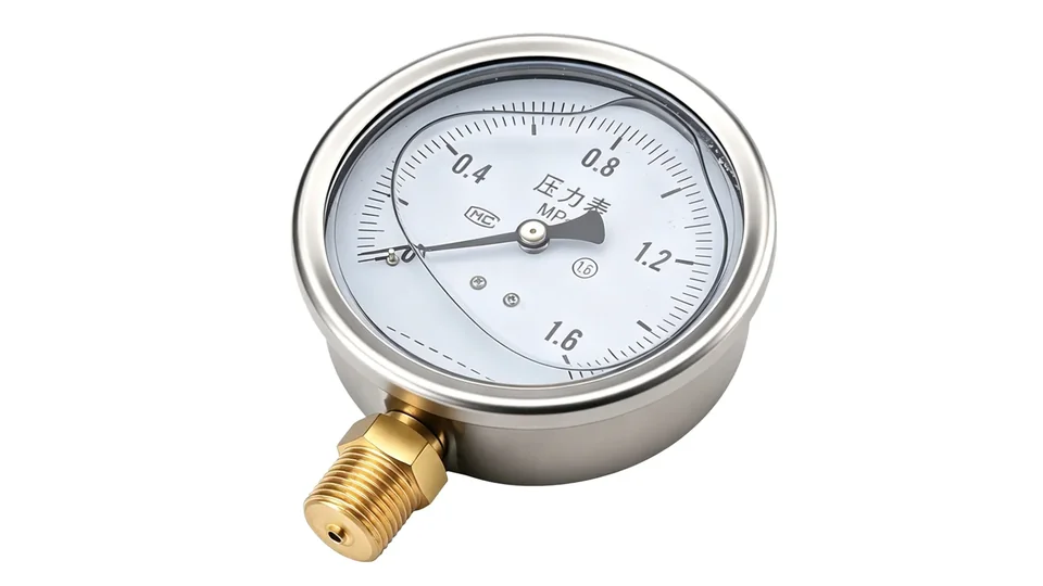
Mekanik manometre doğruluğu, anlık okumanın değil, tam skalanın (span) bir yüzdesi olarak belirtilir. EN 837-1 standardındaki doğruluk sınıfları — 0.1, 0.25, 0.6, 1.0, 1.6, 2.5 ve 4.0 — hepsi span'a atıfta bulunur. Bu nedenle, izin verilen hata mühendislik birimleri cinsinden kadran boyunca sabit kalırken, ölçtüğünüz basınç sabit kalmaz.
Sonuç nettir: gereğinden büyük aralık seçimi, tam da önemsediğiniz noktada hatayı katlar. 100 bar okuyan bir sınıf 1.6 manometre şu şekilde davranır:
| Çalışma basıncı | Tam skala aralığı | Kadrandaki çalışma noktası | İzin verilen hata, sınıf 1.6 | Okumanın %'si olarak hata |
|---|---|---|---|---|
| 100 bar | 160 bar | %62.5 | ±2.56 bar | ±%2.6 |
| 100 bar | 250 bar | %40.0 | ±4.00 bar | ±%4.0 |
| 100 bar | 400 bar | %25.0 | ±6.40 bar | ±%6.4 |
| 100 bar | 600 bar | %16.7 | ±9.60 bar | ±%9.6 |
İki dezavantaj bir araya gelir. Çalışma noktasındaki göreceli hata, gereğinden büyük seçimle doğru orantılı olarak artar, bu nedenle "güvenlik için bir boy büyük" seçilen bir gösterge, kendi görev noktasında ölçülebilir derecede daha kötü performans gösterir. Ayrıca, ibre skalanın alt kısmında durur; burada bölmeler fiziksel olarak aynı boyutta olsa da okumanın daha büyük bir payını temsil eder, bu nedenle çözünürlük de aynı anda düşer. Gereğinden büyük aralık seçimi doğruluğa iki kez mal olur ve kadrana değil, aksesuarlara ait olması gereken bir koruma sağlar.
%75 ve %65 Katsayılarının Kaynağı
EN 837-2, Basınç ölçerler — Bölüm 2: Basınç ölçerler için seçim ve montaj tavsiyeleri, maksimum basınç yükünün durağan yük altında tam skala değerinin %75'ini, dalgalı yük altında ise %65'ini aşmamasını tavsiye eder. Bu bir üretim gerekliliği değil, bir seçim tavsiyesidir ve formüldeki bölenin 0.75 veya 0.65 olmasının nedeni budur.
İfadeye dikkat etmek gerekir. Katsayı, normal çalışma basıncına değil, göstergenin göreceği maksimum yüke uygulanır. "Çalışma basıncını tam skalanın %25 ila %75'i arasında tutun" diyen bir kılavuz, iki farklı değişkeni birleştirir: normal basıncı span'ın %70'inde olan ve geçici piklerin %95'e ulaştığı bir sistem, normal rakam kabul edilebilir görünse bile bu tavsiyeyi karşılamaz.
Üretici seçim literatürü ayrıca normal çalışma basıncının kadranın orta üçte birlik kısmına, yani span'ın yaklaşık %33 ila %66'sına yerleştirilmesini tavsiye eder. Bunu, alıntı yapabileceğiniz bir madde olarak değil, okunabilirlik için yaygın olarak tavsiye edilen bir uygulama olarak kabul edin ve boyutlandırma kuralı olarak değil, 6. adım kontrolü olarak kullanın. İkisi farklı sorunları çözer: katsayı elastik elemanı korur, orta üçte birlik kısım ise okumayı korur.
EN 837-1 Doğruluk Sınıflarını İnceleyin→Standart Ölçüm Aralıkları, Yukarı Yuvarlama ve Birim Dönüşümü
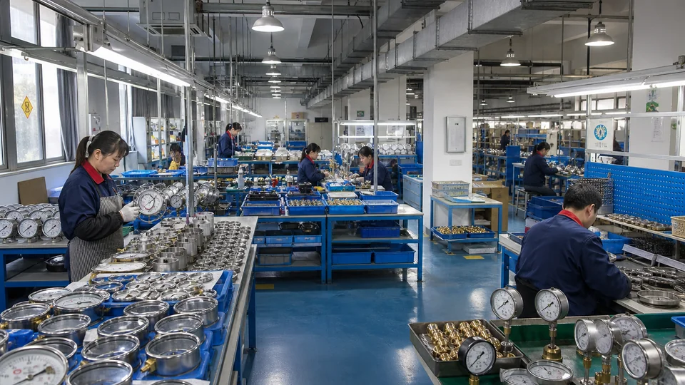
Kadranlar seri üretimde basılır, bu nedenle ölçüm aralıkları sizin hesaplamanızdan değil, ondalık bir seriden gelir. Yaygın kataloglarda kullanılan seri, her onluk basamakta 1, 1.6, 2.5, 4 ve 6 olarak ilerler: 1, 1.6, 2.5, 4, 6, 10, 16, 25, 40, 60, 100, 160, 250, 400, 600 ve 1000 bar. Hesaplanan minimum 267 bar, sipariş edilen 400 bar'lık bir aralığa dönüşür.
Bu yuvarlama adımının bir bedeli vardır. 267'den 400 bar'a çıkmak, çalışma noktasını kadranda daha aşağıya çeker ve oradaki hatayı aynı oranda artırır. Bu nedenle 7. adım, hesapladığınız rakam üzerinden değil, sipariş edeceğiniz aralık üzerinden tekrarlanmalıdır. Sıçramanın büyük olduğu durumlarda, daha yüksek bir doğruluk sınıfı genellikle daha ucuz bir düzeltmedir.
Ölçüm aralıkları bölgelere göre farklı birimlerde belirtilir, bu nedenle bir spesifikasyona karşı katalogları karşılaştırmadan önce birim dönüşümü yapın.
| 1 bar eşittir | Değer |
|---|---|
| psi | 14.5038 |
| MPa | 0.1 |
| kPa | 100 |
| kgf/cm² | 1.0197 |
Çözümlü Örnek 1: Pompa Çıkışı, Durağan Yük
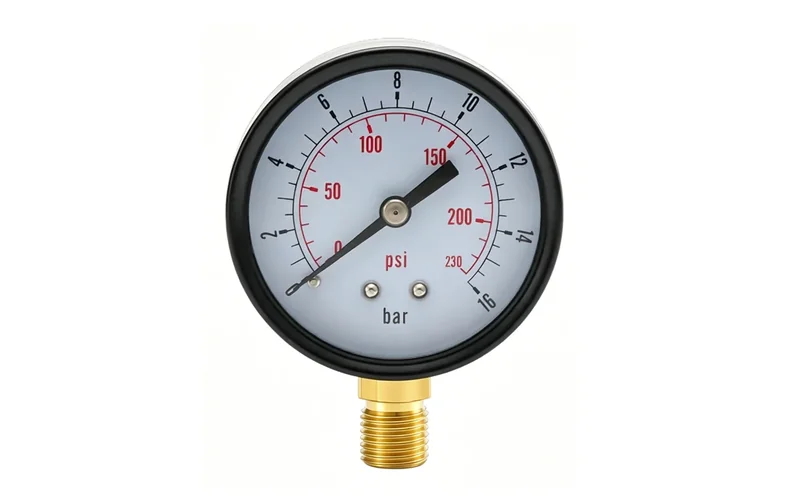
Bir santrifüj pompa normal çalışmada 8 bar basar. Pompa eğrisi, çıkış manometresinin güvenilir bir şekilde görebileceği en yüksek basınç olan 12 bar'a eşdeğer bir kapama yüksekliği verir ve hizmet durağandır.
Durağan yük katsayısına bölmek 12 ÷ 0.75 = 16.0 bar verir, bu zaten standart bir aralıktır, bu nedenle yuvarlama gerekmez. Normal basınç, 8 ÷ 16 = span'ın %50'sinde, yani orta üçte birlik kısımda rahatça yer alır. Sınıf 1.6'da izin verilen hata 16 × %1.6 = ±0.26 bar veya 8 bar'lık okumanın ±%3.2'sidir.
Bu, işe yarayan bir hesabın şeklidir: maksimum basınç karşılanır, ibre skalanın ortasına yakın durur ve görev noktasındaki hata pompa izlemesi için kabul edilebilirdir. Görev, çalışma noktasında ±%2'den daha iyi bir doğruluk gerektiriyorsa, doğru hamle farklı bir aralık değil, aynı 16 bar aralığında daha yüksek bir doğruluk sınıfı seçmektir. Yerleşim ve bağlantı detayı için santrifüj pompa manometresi seçim kılavuzuna bakın.
Çözümlü Örnek 2: Hidrolik Güç Ünitesi, Darbeli Yük

Bir hidrolik güç ünitesi, emniyet valfi 140 bar'a ayarlanmış şekilde 100 bar'da çalışır. Pompa dalgalanması bunu darbeli bir görev haline getirir ve anahtarlama pikleri kabaca 250 bar'a ulaşır; bu pikleri bir snubber enstrümana ulaşmadan önce sönümler.
Emniyet valfi ayarına göre darbeli yük katsayısıyla boyutlandırma yapmak 140 ÷ 0.65 = 215.4 bar verir, bu da standart 250 bar aralığına yukarı yuvarlanır. Normal basınç 100 ÷ 250 = span'ın %40'ına denk gelir ve sınıf 1.6, ±4.0 bar veya 100 bar'lık okumanın ±%4.0'ı kadar hata verir.
İbretlik olan kısım alternatiftir. Sönümlenmemiş 250 bar'lık pike göre boyutlandırma yapmak 250 ÷ 0.65 = 384.6 bar verir, bu da 400 bar'a yukarı yuvarlanır. Bu aralık, çalışma noktasını span'ın %25'ine düşürür ve 100 bar'daki hatayı ±%6.4'e çıkarır. Pikleri absorbe etmek için daha büyük bir kadran satın almak, bir snubber takıp emniyet valfi ayarına göre boyutlandırma yapmaktan görev noktasında %60 daha fazla hataya mal olur. Devre yerleşimi hidrolik manometre seçim kılavuzunda ele alınmıştır.
Çözümlü Örnek 3: Düşük Basınçlı Azot Örtüleme, Hesabın Tutmadığı Durum
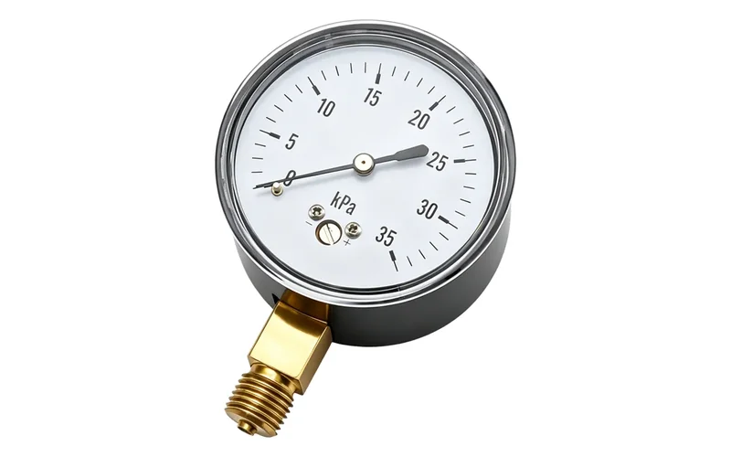
Bir azot örtüleme hattı normal çalışmada 20 mbar basınç tutar ve regülatör bir arıza durumunda güvenilir bir şekilde 50 mbar basabilir. Yük durağandır, bu nedenle 50 ÷ 0.75 = 66.7 mbar, bu da 100 mbar'lık bir kapsül manometre aralığına yukarı yuvarlanır. Normal basınç bu durumda 20 ÷ 100 = span'ın %20'sinde yer alır: orta üçte birlik kısım kontrolü başarısız olur.
Bir sonraki standart aralığa düşmek durumu kurtarmaz. 60 mbar'lık bir aralık çalışma noktasını %33'e koyardı, ancak 60 × 0.75 = 45 mbar, 50 mbar'lık maksimumun altındadır, bu yüzden bunun yerine boyutlandırma tavsiyesini ihlal eder. Hiçbir standart aralık her iki koşulu da sağlamaz, çünkü maksimum basıncın normal basınca oranı 50 ÷ 20 = 2.5'tir.
Hesaplama size ayarlanması gereken değişkenin ölçüm aralığı olmadığını söylüyor. Seçenekler, 60 mbar'lık bir aralığın geçerli olması için maksimumu sınırlayan bir basınç sınırlayıcı veya düşük skaladaki okumayı kabul edip daha yüksek bir doğruluk sınıfı ile ölçüm kalitesini geri kazanmaktır.
| Adım | Pompa çıkışı | Hidrolik güç ünitesi | Azot örtüleme |
|---|---|---|---|
| Pnormal | 8 bar | 100 bar | 20 mbar |
| Pmaks ve kaynağı | 12 bar, kapama yüksekliği | 140 bar, emniyet valfi ayarı | 50 mbar, regülatör arızası |
| Yük tipi ve katsayısı | Durağan, 0.75 | Darbeli, 0.65 | Durağan, 0.75 |
| Hesaplanan minimum | 16.0 bar | 215.4 bar | 66.7 mbar |
| Sipariş edilen standart aralık | 16 bar | 250 bar | 100 mbar |
| Kadrandaki çalışma noktası | %50 ✓ | %40 ✓ | %20 × |
| Çalışma noktasındaki hata, sınıf 1.6 | ±%3.2 | ±%4.0 | ±%8.0 |
Hesaplama Daha Büyük Bir Göstergenin İşe Yaramayacağını Söylediğinde
Üçüncü örnek genelleştirilebilir. Yuvarlamadan önce, çalışma noktası katsayı çarpı Pnormal ÷ Pmaks'a eşittir. Bunun %33'lük okunabilirlik tabanına ulaşmasını gerektirmek, iki basıncın ne kadar ayrı olabileceğini sınırlar: Pmaks ÷ Pnormal oranı, durağan hizmet için yaklaşık 2.3'ü (0.75 ÷ 0.33) veya darbeli hizmet için yaklaşık 2.0'ı (0.65 ÷ 0.33) geçmemelidir. Yukarı yuvarlama çalışma noktasını daha da düşürür, bu nedenle bu yeterli bir koşul değil, gerekli bir koşuldur.
Bu oranın üzerinde hiçbir ölçüm aralığı her iki kuralı da sağlamaz ve cevap, aralığı yükseltmek yerine Pmaks'ı düşürmektir: darbe için bir snubber, ani yükselmeler için bir basınç sınırlayıcı veya geçici piklerin kendisinin yakalanması gereken durumlarda tepe tutma özellikli bir dijital gösterge. Aşırı basınç koruması bir kadran kararı değil, bir aksesuar kararıdır.
Çelişkili gibi görünen iki rakamı ayırmaya değer. EN 837-1, Bourdon tüplü manometreler için basınç limitlerini durağan yükte tam skala değeri, dalgalı yükte tam skalanın 0.9 katı ve kısa süreli yükte tam skalanın 1.3 katı olarak belirtirken, EN 837-2 maksimum yükün %75'in altında tutulmasını tavsiye eder. Birincisi enstrümanın neye dayandığını tanımlar; ikincisi ise hizmet ömrü, sıfır kararlılığı ve okunabilirlik için neyin seçileceğini belirtir. Standart ayrıca tam skalada yüklenebilir ve tam skalada yüklenemez tasarımları da ayırt eder, bu nedenle belirli model için limiti veri sayfasından teyit edin.
Ölçüm Aralığı Hesabının Karar Veremeyeceği Konular
Bu prosedür bir kadranı boyutlandırır. Girdileri doğrulamaz. Pmaks, akışkan, sıcaklık ve yükün gerçekten durağan olup olmadığı gibi konuların hepsi proses tarafından gelir ve iyimser bir maksimumdan hesaplanan bir aralık, ne kadar dikkatli yuvarlanırsa yuvarlansın yanlıştır.
Ölçüm aralığını doğru belirlemek de seçimi tamamlamaz. Islanan malzeme, proses bağlantısı, dolgu, giriş koruması, kadran boyutu ve tehlikeli alan, oksijen veya hijyenik gereklilikler ayrı kararlardır ve doğru aralıkta seçilmiş ancak yanlış malzemeden yapılmış bir gösterge yine de arızalanır.
Emniyet valfi ayarları ve tasarım basınçları proses ve ekipman mühendisliğine aittir: manometre seçimi bu rakamları okur, asla değiştirmez. Güvenlikle ilgili hizmetler için, sorumlu mühendisin aralığı, aksesuar ayar noktalarını ve malzemeleri onaylamasını sağlayın.
Önemli çıkarımlar
- Ölçüm aralığını, güvenilir maksimum basıncı durağan yük için 0.75'e veya darbeli yük için 0.65'e bölerek boyutlandırın, ardından standart bir aralığa yukarı yuvarlayın.
- Doğruluk, span'ın bir yüzdesidir, bu nedenle gereğinden büyük bir aralık seçimi çalışma noktasındaki hatayı doğru orantılı olarak artırır.
- Maksimum basınç normal basıncı yaklaşık 2.3 kattan (darbeli için 2.0) fazla aşıyorsa, hiçbir ölçüm aralığı her iki kuralı da sağlamaz ve çözüm bir aksesuardır.
- Hesaplama yalnızca bir kadranı boyutlandırır: P_maks, akışkan, sıcaklık ve güvenlikle ilgili ayarlar sorumlu proses mühendisi tarafından onaylanmalıdır.
Related buyer pages
Industrial pressure gauge manufacturerMatch the calculated working range to standard 0-1 to 0-1000 bar dial ranges before issuing an RFQ.
Custom pressure gauge manufacturerOrder non-standard ranges, dual-scale dials and psi/bar/MPa combinations when catalogue ranges do not fit.
İlgili yazılar
- Yangın Sprinkler Manometresi Gereksinimleri: UL 393 ve NFPA 25
Yangın sprinkler manometresi gereksinimleri: NFPA 13 neden UL 393 listeli veya FM onaylı manometre ister, ölçüm aralığı ve skala seçimi, NFPA 25 değiştirme kuralları.
- Manometre Doğruluk Sınıfı Seçimi: 4 Temel Değişken
Manometre doğruluk sınıfı seçimi: EN 837-1 sınıflarının izin verdiği hata, ölçüm aralığı ve çalışma noktasının etkisi, her görev için doğru sınıf.
- Vakum Manometresi Seçimi: Kompound Aralık ve Sınırlar
Vakum manometresi seçimi: efektif, vakum, kompound ve mutlak basınç referansları, her vakum seviyesine uygun algılama elemanı ve mekanik kadranın bittiği nokta.
- Emniyet Ventili Manometresi: Aralık ve Montaj Konumu
Basınçlı kaplar, pompa skidleri, basınçlı hava ve kazan sistemleri için emniyet ventili manometre seçim rehberi: ölçüm aralığı, ayar basıncı payı, karşı basınç, patlama diski ve güvenli montaj kontrolleri.
Sık sorulan sorular
Daha büyük bir manometre ölçüm aralığı daha mı güvenlidir?
Hayır. Doğruluk tam skalanın bir yüzdesidir, bu nedenle büyük aralık seçimi çalışma noktanızdaki hatayı artırır. 100 bar okuyan bir sınıf 1.6 manometre, 160 bar'lık bir aralıkta okumanın ±%2.6'sı kadar hata verirken, 400 bar'lık bir aralıkta ±%6.4 hata verir. Ani basınç yükselmelerine karşı koruma, daha büyük bir kadrana değil, snubber'lara ve sınırlayıcılara aittir.
400 bar'lık bir manometre 100 bar'da neden hassas değildir?
Sınıf 1.6, 400 bar'lık span'ın ±%1.6'sı anlamına gelir, bu da kadranın her yerinde ±6.4 bar demektir. 100 bar'lık bir okumada bu sabit ±6.4 bar, okunan değerin ±%6.4'üdür, oysa aynı mutlak hata 250 bar'da sadece ±%2.6 olurdu.
%75 kuralı bir standart gerekliliği midir?
Bir gereklilik değil, bir tavsiyedir. Standardın seçim ve montaj bölümü olan EN 837-2, maksimum basınç yükünün durağan yük altında tam skalanın %75'inin ve dalgalı yük altında %65'inin altında kalmasını tavsiye eder. Bu, normal çalışma basıncına değil, maksimum yüke uygulanır.
Hesaplanan aralık standart bir aralık değilse ne olur?
1, 1.6, 2.5, 4, 6 ondalık serisindeki bir sonraki aralığa yukarı yuvarlayın, ardından doğrulamayı sipariş edeceğiniz aralık üzerinden tekrarlayın. Yukarı yuvarlama, çalışma noktasını düşürür ve oradaki hatayı aynı oranda artırır.
Kompaund veya vakum manometresi için aralığı nasıl hesaplarım?
Aynı katsayıları kullanın, ancak çalışma noktası kontrolünü tüm span'a göre yapın. -1 ila 0 ila 15 bar'lık bir kadran 16 bar'lık bir span'a sahiptir, bu nedenle 5 bar'lık bir çalışma basıncı, pozitif bölümün üçte birinde değil, 6 bar'lık span'da veya %37.5'te yer alır.
Katalogları karşılaştırırken bar aralığını psi'ye nasıl çeviririm?
14.5038 ile çarpın. 16 bar'lık bir aralık 232 psi ve 250 bar 3626 psi'dir, bu yüzden kataloglardaki psi aralıkları düzensiz görünür: bunlar bar serisinin dönüşümleridir. 1 bar ayrıca 0.1 MPa, 100 kPa ve 1.0197 kgf/cm²'ye eşittir.