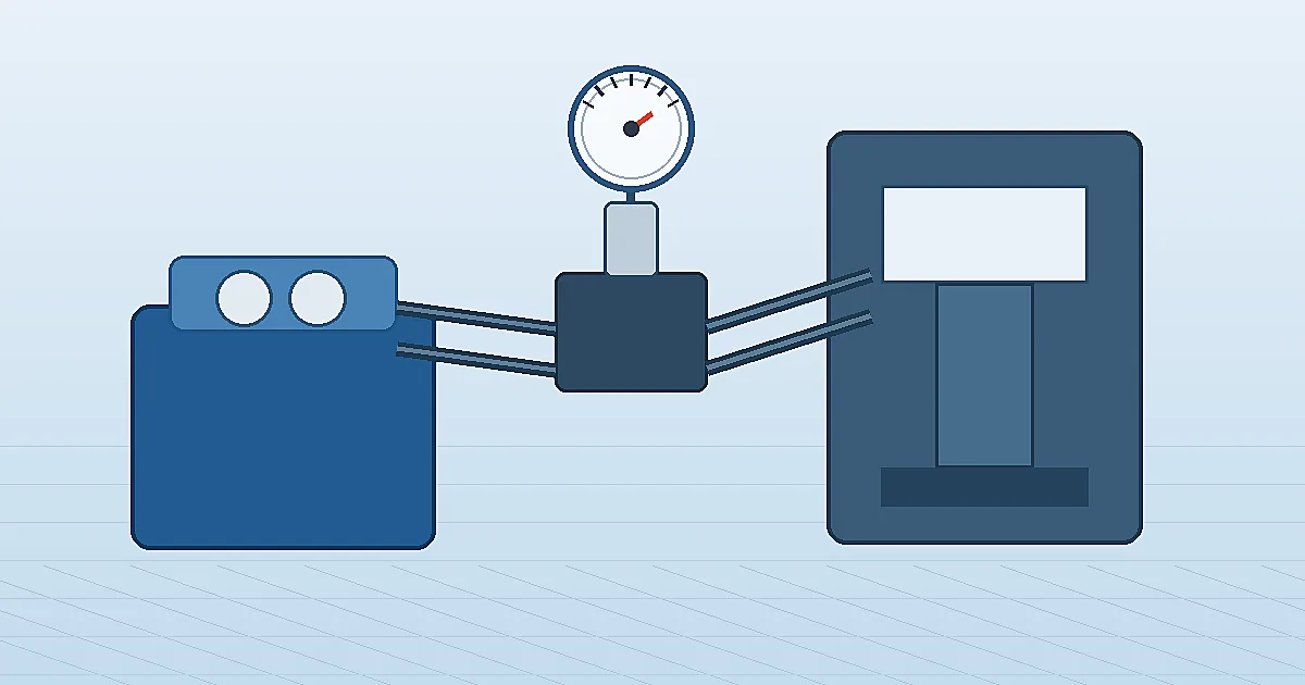
Выбор манометра для гидравлики означает подбор прибора под диапазон давления, пульсацию, вибрацию, рабочую жидкость, присоединение и задачу обслуживания. В прессах, гидростанциях, мобильной технике и испытательных стендах манометр часто быстрее всего показывает состояние насоса, настройку клапана, загрязнение фильтра или сопротивление исполнительного механизма. Показание полезно только тогда, когда диапазон, защита и монтаж соответствуют реальному контуру.
Почему выбор манометра для гидравлики отличается
Выбор манометра для гидравлики отличается от воды, воздуха и низкого давления, потому что гидравлические контуры сочетают высокое статическое давление, резкие пики, пульсацию насоса, удар клапанов и вибрацию машины. Пресс, термопластавтомат, гидростанция или мобильная машина могут долго работать при стабильном давлении, а затем получить короткий скачок при зажиме, реверсе или срабатывании предохранительного клапана.
ISO описывает ISO 4413:2010 как международный стандарт общих правил и требований безопасности для гидравлических систем и компонентов машин. Манометр является только одним элементом, но он тоже должен соответствовать рабочему давлению, рискам, доступу для обслуживания и надежной работе. См. также сравнение сухих и заполненных манометров и руководство по демпферу пульсаций.
Смотреть варианты гидравлических манометров →Более 143 промышленных моделей→Размещайте манометры в точках принятия решений
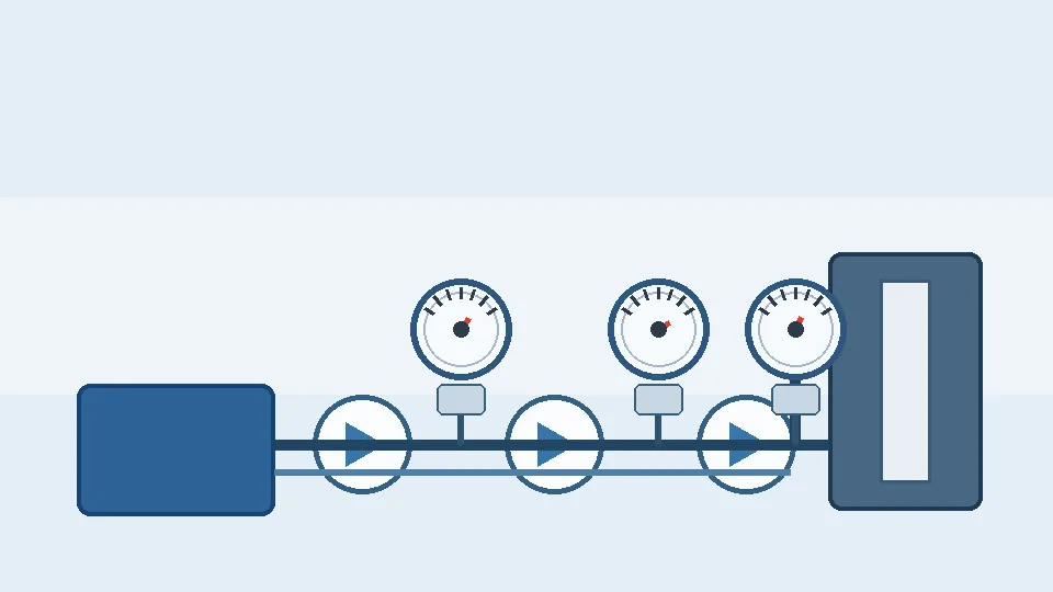
Полезный манометр гидросистемы ставят там, где показание помогает принять решение: выход насоса, выход редукционного клапана, линия аккумулятора, перепад на фильтре, тестовый порт блока клапанов или рабочая линия цилиндра. Манометр далеко после клапана может быть видимым, но слабым для диагностики насоса. Манометр прямо на вибрирующем корпусе насоса может быстро выйти из строя.
| Точка измерения | Что помогает оценить | Типичный прибор |
|---|---|---|
| Выход насоса или главная напорная линия | Выход насоса, настройка клапана, пики, базовое давление | Заполненный манометр Бурдона, демпфер при сильной пульсации |
| Тестовый порт блока | Настройка клапана, диагностика, пусконаладка | Компактный гидравлический манометр с тестовым соединением |
| Линия аккумулятора | Заряд/разряд и проверка изоляции | Манометр выше максимального давления с запорным клапаном |
| Вход/выход фильтра | Загрязнение элемента и риск байпаса | Дифференциальный манометр или пара локальных приборов |
Choose range for normal pressure, relief pressure and spikes
Correct range selection for a hydraulic pressure gauge starts with three numbers: normal working pressure, relief-valve setting and the highest spike the system generates. A common engineering rule is to keep normal working pressure in the middle third of the dial (25–75% of full scale) so the Bourdon tube operates within its elastic region and pointer accuracy stays within specification. A gauge installed at 90% of its range during normal operation will drift, fatigue and fail faster than one operating in its linear zone.
The relief-valve setting typically sits 10–20% above normal working pressure. Select a gauge whose full-scale range clears the relief setting with margin. For example, a 210 bar working pressure system with a 230 bar relief setting suits a 400 bar full-scale gauge, keeping normal pressure at 52% and relief pressure at 57% of span — both comfortably within the middle zone.
Pressure spikes during clamping, valve shock and end-of-stroke events can be two to five times normal pressure and last only milliseconds. A snubber or restrictor damps these spikes from the Bourdon tube, but the gauge range must still accommodate any spike the snubber allows through. If spikes are severe and a snubber is not fitted, size the range to the spike maximum and accept reduced readability at normal pressure, or use a digital gauge with peak-hold to capture spike values without over-ranging a Bourdon instrument.
| System characteristic | Range selection guidance |
|---|---|
| Normal working pressure well below relief | Size to 2× normal pressure; keeps normal reading at ~50% FS |
| Normal pressure close to relief setting | Size so relief pressure ≤ 75% FS; accept lower normal-pressure resolution |
| Severe spike events (valve slam, press reversal) | Add snubber and size to spike maximum, or use digital gauge with peak-hold |
| Variable duty cycle (low idle + high load) | Consider two gauges at different ports or a dual-scale dial |
Требования к классу точности для гидравлических манометров
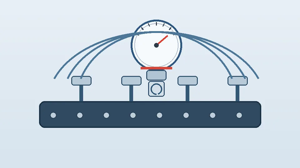
Класс точности задаётся в процентах от всего диапазона шкалы (Full Scale), а не от текущего показания. Гидравлический манометр диапазоном 400 бар класса 1,6 по EN 837-1 имеет допускаемую погрешность ±6,4 бар по всей шкале. При рабочем давлении 250 бар это ±2,6% от рабочего показания.
| Класс EN 837-1 | Класс ASME B40.100 | Полоса погрешности | Гидравлическое применение |
|---|---|---|---|
| 0,6 | Grade 2A | ±0,6% FS | Испытательные стенды, сервоцилиндры |
| 1,0 | Grade 1A | ±1,0% FS | Контроль усилия пресса, приёмо-сдаточные испытания |
| 1,6 | Grade B | ±1,6% FS | Общие гидравлические контуры — стандартный выбор |
| 2,5 | Grade C | ±2,5% FS | Только приблизительный контроль |
Класс 1,6 подходит для большинства гидравлических применений. Манометры класса 1,0 необходимы при жёстких допусках на усилие пресса или требованиях приёмочных протоколов.
Вибрация снижает фактическую точность быстрее, чем указано в паспорте. Маслозаполненные корпуса и демпферы защищают механизм и сохраняют номинальную точность.
Указывайте класс в заявке на поставку. На шкале EN 837-1 указан числовой класс (например, «1,6»); ASME B40.100 — буквенное обозначение (например, «Grade B»). Всегда явно указывайте класс в технических требованиях.
Liquid-filled gauges, snubbers and stainless wetted parts
Three design choices together determine whether a hydraulic pressure gauge survives its service life: fill fluid, pulsation damping and wetted-parts material.
Liquid fill. Glycerin (glycerol) is the standard fill fluid for hydraulic gauges operating between −5 °C and +65 °C. It damps pointer flutter caused by pump ripple, reduces friction on the Bourdon tube pivot bearings, and delays fatigue cracking by cushioning shock. For temperatures below −5 °C, a silicone oil fill (typically dimethylpolysiloxane) retains mobility where glycerin would become viscous. For food-grade and pharmaceutical-adjacent hydraulics, NSF H1 or FDA-compliant food-grade fill is specified. Never use glycerin where the fluid may contact water-glycol hydraulic fluid — glycerin can absorb water and dilute the system.
Snubbers. A pulsation snubber installs between the hydraulic port and the gauge inlet to restrict the rate at which pressure can rise inside the Bourdon tube. Sintered (porous-plug) snubbers provide consistent resistance and are less prone to fouling than orifice-disc types in clean hydraulic oil service. Adjustable orifice snubbers allow the restriction to be matched to the pulsation frequency. Snubber restriction must not be so high that it filters out a genuine pressure event that an operator needs to see.
Wetted-parts material. Standard hydraulic gauges use steel or brass Bourdon tubes. For water-glycol hydraulic fluids, phosphate ester fluids or any moisture-contaminated system, specify 316L stainless steel wetted parts. Brass is attacked by water-based hydraulic fluids and will fail prematurely. Where the hydraulic medium is a specialty fluid (bio-hydraulic oil, polyglycol), verify chemical compatibility of all elastomers and metals against the fluid's safety data sheet before specifying a standard gauge.
Installation details for presses, power units and manifolds
Mounting location, process connection and isolation determine long-term gauge reliability as much as gauge specification does.
Isolation valve. Always fit an isolation valve (needle valve or block-and-bleed valve) between the pressure port and the gauge. Without isolation, replacing a failed gauge on a live hydraulic circuit requires depressurising the entire system. A simple needle valve allows the gauge to be isolated, removed and replaced while the system remains pressurised. Specify a valve with a rated working pressure at least equal to the system relief setting.
Process connection torque. Hydraulic gauge connections (typically 1/4 BSP, 1/4 NPT or 1/4 SAE straight thread) must be torqued to fitting-manufacturer specifications, not hand-tightened. Under-torquing causes leaks; over-torquing can crack the gauge socket or distort the Bourdon tube anchor, introducing a zero error. Use a crow-foot or open-end spanner — never apply torque to the gauge case or window.
Orientation. Liquid-filled gauges should be mounted with the dial face vertical (12 o'clock stem up or angled, not lying flat). Horizontal stem mounting is acceptable for manifold or back-mounted gauges, but filling the case partially with glycerin on a flat-mounted gauge creates an air pocket that reduces damping effectiveness. If a flat-mount position is unavoidable, bleed the gauge case during installation to remove trapped air.
Vibration isolation. On pump bodies or vibrating structures, soft-mount the gauge with a stainless braided hose flexible connector between the rigid port and the gauge. The hose absorbs vibration that would otherwise fatigue the Bourdon tube and loosen the case. Specify hose rated above system working pressure with a burst pressure well above the relief setting.
Accessibility. Place gauges where an operator can read them without obstruction from machine guards or hydraulic cylinders. A gauge that cannot be read without opening a guard will not be read during operation, defeating its purpose. Mark normal operating pressure and maximum allowable pressure on the dial bezel with a permanent marker or adhesive arc label.
Границы риска: чего гидравлический манометр не доказывает
Манометр сам по себе не доказывает расход, чистоту масла, усилие цилиндра, предзаряд аккумулятора или состояние клапана. Он не покажет миллисекундный пик, если механизм и демпфер слишком медленные. Он также не делает безопасными шланг, фитинг или блок с недостаточным рейтингом. Нормальное давление может скрывать малый расход, воздух в масле, тепловой дрейф, внутреннюю утечку или забитую обратную линию.
Для прессов, подъемного оборудования, опасного движения, давления выше обычных каталогов, огнестойких жидкостей, кислородных зон или взрывоопасных участков используйте эту статью только как справочник. До заказа подтвердите давление, защиту от разрыва, совместимость материалов, стандарты, ограждения и испытания с OEM и инженером площадки. Manogauge может помочь с подбором на базе производства в Чжэцзяне, но окончательная пригодность определяется проектной спецификацией.
Hydraulic pressure gauge selection checklist
Use this checklist to confirm specification before ordering a replacement or new hydraulic pressure gauge. A gauge that fails three or more of these checks will likely fail early or give misleading readings.
| Check | Requirement | Notes |
|---|---|---|
| Normal working pressure in range? | 25–75% of gauge full scale | Prevents fatigue and over-range failure |
| Relief setting within range? | ≤ 75% of full scale | Allows safe exposure without overpressure |
| Spike protection? | Snubber fitted or range covers spike | Unprotected spikes are the main cause of early failure |
| Fill fluid compatible? | Glycerin, silicone or food-grade as required | Verify against temperature range and fluid type |
| Wetted material compatible? | Steel for oil; SS316L for water-based fluids | Brass corrodes in water-glycol |
| Isolation valve fitted? | Yes — always | Required for safe replacement under pressure |
| Connection thread matches? | Same standard (BSP/NPT/SAE) and size | Never force unlike threads |
| Accuracy class sufficient? | ≥ 1.6% FS for monitoring; ≥ 1.0% for control loops | Use tighter class only if process requires it |
| Dial legible from operating position? | Yes | 100 mm dial minimum for distances > 2 m |
| Spare gauge available? | Yes — at least 1 | Critical circuits need a local spare |
Hydraulic gauge failure modes and replacement triggers
Knowing what hydraulic pressure gauge failures look like helps maintenance teams replace instruments before a misleading reading causes a process fault or a safety incident.
Pointer frozen or sluggish. A pointer that does not return to zero when pressure is released, or moves slowly during rapid pressure changes, usually indicates a blocked snubber orifice. Remove and clean or replace the snubber before condemning the gauge. If the snubber is clear, the Bourdon tube may be internally fouled or the pivot is worn.
Permanent zero offset. If the pointer rests above zero with no system pressure, the Bourdon tube has been overpressurised and taken a set beyond its elastic limit. The gauge is unserviceable: its indicated reading is now wrong by the zero offset at every point in the range. Replace immediately and identify the root cause of the overpressure event.
Fogged or discoloured lens. Glycerin expands with heat and, if the gauge is sealed, may leak through the case back seal or around the fill plug. A fogged lens typically means the fill fluid has emulsified with water contamination or has begun to deteriorate. A milky appearance inside the case is a sign of water ingress — replace the gauge and investigate whether the hydraulic fluid itself is contaminated.
Glycerin leak. Liquid-filled gauges with a leak at the process connection or case back lose their damping protection and will fail from vibration fatigue at an accelerated rate. A small external glycerin stain is a warning; a gauge that has lost most of its fill should be replaced, not topped up in the field.
Cracked or shattered window. Inspect after any overpressure event. A cracked window is a hazard if the Bourdon tube fails — replace the gauge if the window is not intact.
Set a planned replacement interval based on duty severity: two to three years for normal industrial duty, annually for severe pulsation or high-cycle press applications, and on-condition for accessible critical monitoring points.
Specifying hydraulic gauges for procurement and maintenance planning
A clear purchase specification reduces error rate when ordering replacement gauges and helps stockroom staff confirm a stored spare matches what is installed.
Minimum specification line items. A complete hydraulic gauge specification states: pressure range (e.g. 0–400 bar), dial size (63 mm, 100 mm or other), process connection thread type and size (e.g. 1/4 BSP male, centre-back), accuracy class (e.g. ±1.6% FS to EN 837), case material (steel, stainless steel or brass), fill type (glycerin-filled or dry), wetted-parts material (steel, 316L SS or brass) and any certification requirement (SIL, ATEX, PED).
Interchangeability documentation. When a gauge is installed on a machine, tag it with the full specification and stock code. Photograph the nameplate and store the image in the maintenance management system. A photograph prevents the common error of replacing a 400 bar gauge with a 250 bar gauge of the same physical size.
Stocking strategy. For hydraulic circuits with four or more gauges of the same specification, holding two spare gauges locally is justified. For single-unit special specifications (e.g. food-grade fill, stainless case), hold one spare and know the lead time from supplier. A gauge failure on a critical press that causes production downtime for 48 hours while a replacement is sourced is far more expensive than the cost of a spare.
Calibration and traceability. Hydraulic system gauges used only for operational monitoring (not safety or SIL) do not normally require formal calibration records. Gauges used to set relief valves, verify proof-test pressures or support regulatory inspection should have a calibration certificate traceable to national measurement standards. Specify this requirement at purchase — a gauge supplied with a certificate of conformance (CoC) and one with a UKAS/DAkkS calibration certificate are not the same document.
Сопутствующая продукция
- Liquid-Filled Pressure Gauge - Radial (ZX-06-R) — 0–60 MPa
- Shock-Resistant Pressure Gauge - Radial (ZX-03-R) — 0–270 psi
- Stainless Steel Pressure Gauge - Radial (ZX-01-R) — 0–100 MPa
Часто задаваемые вопросы
Какой диапазон выбрать для гидравлического манометра?
Начните с рабочего давления, настройки предохранительного клапана и возможных пиков. Нормальное давление должно быть в читаемой средней части шкалы с запасом на скачки и пределы OEM.
Лучше ли заполненный манометр для гидравлики?
Обычно да, если есть вибрация или пульсация насоса. Заполнение гасит дрожание стрелки и износ механизма, но нужно подтвердить температуру, жидкость и скорость отклика.
Когда гидравлическому манометру нужен демпфер?
Демпфер или дроссель применяют, когда пульсация насоса или удар клапана вызывает дрожание стрелки или ранний отказ. Не ограничивайте слишком сильно, если нужно видеть быстрые события.
Может ли манометр доказать расход гидросистемы?
Нет. Давление помогает диагностике, но расход требует расходомера или данных машины. Нормальное давление может скрывать утечку, малый расход или забитый слив.
Какие присоединения бывают у гидравлических манометров?
Используются NPT, BSP, G и метрические резьбы. До установки сверяйте реальный порт или тестовую муфту и не соединяйте разные формы резьбы силой.
Как часто следует заменять гидравлические манометры?
Замена по состоянию, а не по фиксированному календарю. При тяжёлых пульсациях или высоких циклических нагрузках — проверка ежегодно, замена каждые два-три года. В малонагруженных контурах манометры служат пять и более лет. Немедленная замена после подтверждённого превышения давления или при нулевом смещении стрелки.
Можно ли использовать сухой манометр в гидравлической системе?
Сухой манометр может работать кратковременно, но при пульсации насоса или гидравлическом ударе выйдет из строя быстрее, чем жидкостный. Отсутствие демпферной жидкости ускоряет усталость трубки Бурдона и износ подшипников. В гидравлических системах при наличии вибрации или пульсаций следует использовать жидкостные манометры.
Какую жидкость заливать в высокоинтенсивный гидравлический манометр?
Для минерального масла в диапазоне от −5 °C до +65 °C стандартная заливка — глицерин. В холодных условиях — силиконовое масло. Для водогликолевых или фосфатноэфирных гидрожидкостей — манометр из нержавеющей стали с заливкой силиконовым маслом: глицерин несовместим с водными жидкостями.
Нужен ли гидравлическому манометру сертификат калибровки?
Манометры для оперативного контроля (считывание давления оператором) обычно не требуют формальной калибровки. Манометры для настройки предохранительных клапанов, проверки испытательных давлений или соответствия нормативным требованиям должны иметь сертификат калибровки с прослеживаемостью к национальным стандартам.