
A seleção da faixa de um manômetro tem uma resposta definida: divida a pressão máxima plausível por 0,75 em serviço estático ou por 0,65 em serviço pulsante, arredonde para a faixa padrão mais próxima e confirme que a pressão normal de trabalho continua no terço central do mostrador. Este guia traz a fórmula e sua origem na EN 837-2, a série de faixas padrão, três exemplos totalmente resolvidos em bar e milibar, e a razão a partir da qual ampliar a faixa deixa de ajudar.
A fórmula para a faixa do manômetro
A seleção da faixa de um manômetro é uma questão de aritmética, uma vez que se tenha um número do lado do processo: a pressão mais alta que o instrumento realmente irá registrar. A fórmula de trabalho é faixa mínima de fundo de escala = pressão máxima crível ÷ 0.75 para carga estável, ou ÷ 0.65 para carga pulsante. Arredonde o resultado para a faixa padrão mais próxima e, em seguida, verifique-o.
- Estabeleça a pressão normal de operação (Pnormal).
- Estabeleça a pressão máxima crível (Pmax): arranque, pressão de shut-off da bomba, comutação de válvulas, ajuste da válvula de alívio.
- Decida se a carga é estável ou pulsante.
- Divida Pmax por 0.75 para serviço estável, ou por 0.65 para serviço pulsante.
- Arredonde para a faixa de fundo de escala padrão mais próxima.
- Verifique se Pnormal ainda se enquadra no terço central do mostrador, aproximadamente 33–66% do fundo de escala.
- Verifique a exatidão no ponto de trabalho: fundo de escala × classe de exatidão ÷ Pnormal.
Os passos 6 e 7 são os que a maioria dos guias de seleção omite. O arredondamento para cima empurra sempre o ponto de trabalho para uma posição mais baixa no mostrador, pelo que a faixa que encomenda nunca é exatamente a faixa que calculou.
Ver faixas de manômetros no catálogoMais de 143 modelos de manômetros industriais→Por que a faixa é uma decisão de exatidão, não de segurança
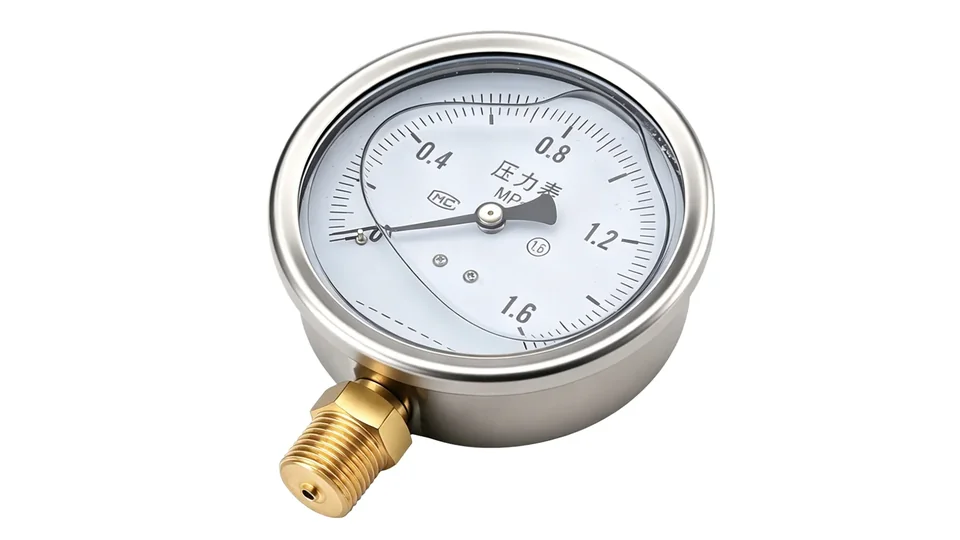
A exatidão de um manômetro mecânico é expressa como uma percentagem do fundo de escala (span), e não da leitura instantânea. As classes de exatidão na norma EN 837-1 — 0.1, 0.25, 0.6, 1.0, 1.6, 2.5 e 4.0 — referem-se todas ao span, pelo que o erro permitido permanece constante em unidades de engenharia ao longo de todo o mostrador, enquanto a pressão que está a medir não.
A consequência é direta: o sobredimensionamento multiplica o erro exatamente onde este é importante. Um manômetro de classe 1.6 com uma leitura de 100 bar comporta-se desta forma.
| Pressão de trabalho | Faixa de fundo de escala | Ponto de trabalho no mostrador | Erro permitido, classe 1.6 | Erro como % da leitura |
|---|---|---|---|---|
| 100 bar | 160 bar | 62,5% | ±2,56 bar | ±2,6% |
| 100 bar | 250 bar | 40,0% | ±4,00 bar | ±4,0% |
| 100 bar | 400 bar | 25,0% | ±6,40 bar | ±6,4% |
| 100 bar | 600 bar | 16,7% | ±9,60 bar | ±9,6% |
Acumulam-se duas penalizações. O erro relativo no ponto de trabalho aumenta em proporção direta ao sobredimensionamento, pelo que um manômetro escolhido "um tamanho acima por segurança" é mensuravelmente pior no seu próprio ponto de operação. Separadamente, o ponteiro fica na parte inferior da escala, onde as divisões têm fisicamente o mesmo tamanho mas representam uma fatia maior da leitura, pelo que a resolução diminui ao mesmo tempo. O sobredimensionamento custa o dobro da exatidão e compra uma proteção que pertence aos acessórios e não ao mostrador.
A origem dos coeficientes de 75% e 65%
A norma EN 837-2, Manômetros — Parte 2: Recomendações de seleção e instalação para manômetros, recomenda que a carga de pressão máxima não exceda 75% do valor de fundo de escala sob carga estável, ou 65% sob carga flutuante. É uma recomendação de seleção, não um requisito de fabrico, e é a razão pela qual o divisor na fórmula é 0.75 ou 0.65.
A formulação merece atenção. O coeficiente aplica-se à carga máxima que o manômetro irá registrar, e não à pressão normal de operação. A orientação que diz "manter a pressão de trabalho entre 25% e 75% do fundo de escala" funde duas variáveis diferentes: um sistema cuja pressão normal se situa em 70% do span enquanto os transientes atingem 95% não cumpre a recomendação, embora o valor normal pareça aceitável.
A literatura de seleção dos fabricantes recomenda separadamente que a pressão normal de operação se situe no terço central do mostrador, aproximadamente entre 33% e 66% do span. Trate isso como uma prática amplamente recomendada para a legibilidade, e não como uma cláusula que pode citar, e use-a como a verificação do passo 6, em vez de como a regra de dimensionamento. As duas resolvem problemas diferentes: o coeficiente protege o elemento elástico, o terço central protege a leitura.
Ver as classes de exatidão EN 837-1 em detalhe→Faixas padrão, arredondamento e conversão de unidades
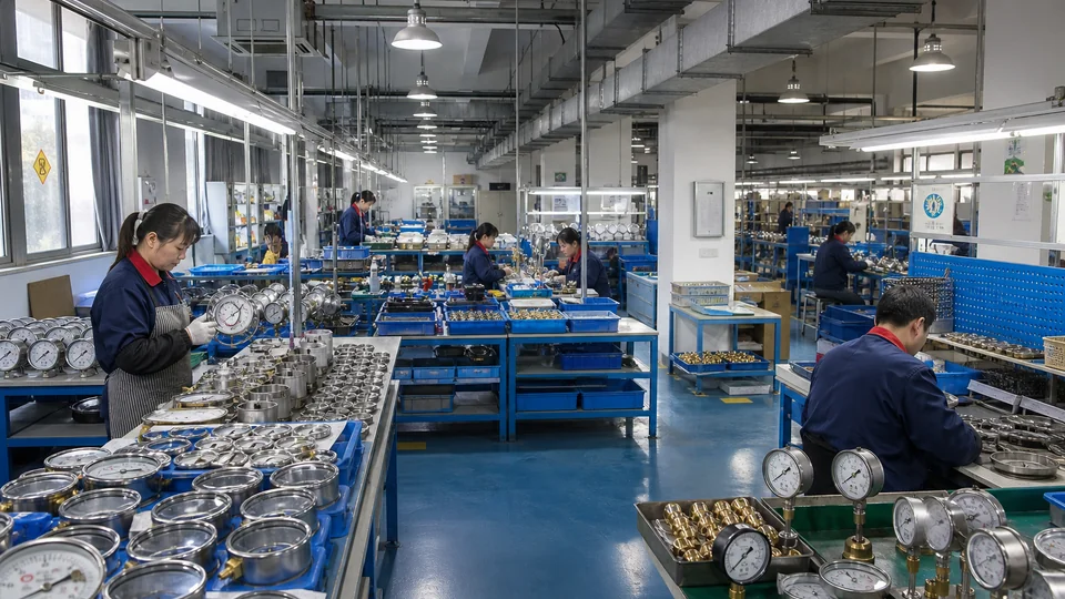
Os mostradores são impressos em lotes de produção, pelo que as faixas provêm de uma série decimal e não do seu cálculo. A série de uso comum em catálogos é 1, 1.6, 2.5, 4 e 6 em cada década: 1, 1.6, 2.5, 4, 6, 10, 16, 25, 40, 60, 100, 160, 250, 400, 600 e 1000 bar. Um mínimo calculado de 267 bar torna-se uma faixa encomendada de 400 bar.
Esse passo de arredondamento não é isento de custos. Passar de 267 para 400 bar baixa o ponto de trabalho no mostrador e aumenta o erro nesse ponto na mesma proporção, razão pela qual o passo 7 deve ser repetido na faixa que irá encomendar e não no número que calculou. Quando o salto é grande, uma classe de exatidão mais rigorosa é geralmente a correção mais barata.
As faixas são cotadas em diferentes unidades por região, pelo que deve converter antes de comparar catálogos com uma especificação.
| 1 bar equivale a | Valor |
|---|---|
| psi | 14.5038 |
| MPa | 0.1 |
| kPa | 100 |
| kgf/cm² | 1.0197 |
Exemplo prático 1: descarga de bomba, carga estável
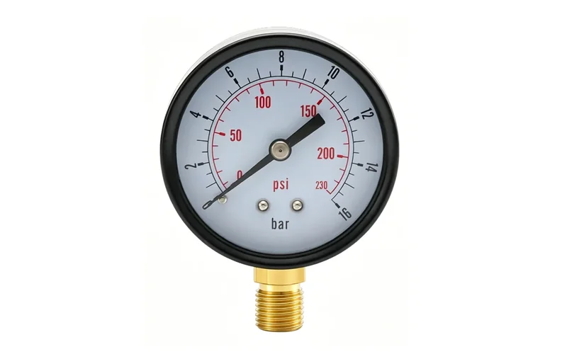
Uma bomba centrífuga fornece 8 bar em operação normal. A curva da bomba indica uma pressão de shut-off equivalente a 12 bar, a pressão mais alta que o manômetro de descarga pode crívelmente registrar, e o serviço é estável.
Dividindo pelo coeficiente de carga estável obtém-se 12 ÷ 0.75 = 16,0 bar, que já é uma faixa padrão, pelo que não é necessário arredondar. A pressão normal situa-se em 8 ÷ 16 = 50% do span, confortavelmente no terço central. Na classe 1.6, o erro permitido é de 16 × 1,6% = ±0,26 bar, ou ±3,2% da leitura de 8 bar.
Esta é a forma de um cálculo que funciona: o máximo está coberto, o ponteiro situa-se perto do meio da escala e o erro no ponto de operação é aceitável para a monitorização da bomba. Se a aplicação exigisse uma exatidão superior a ±2% no ponto de trabalho, a medida correta seria uma classe de exatidão mais rigorosa na mesma faixa de 16 bar, e não uma faixa diferente. Para detalhes de posicionamento e ligação, consulte o guia de seleção de manômetros para bombas centrífugas.
Exemplo prático 2: unidade de potência hidráulica, carga pulsante

Uma unidade de potência hidráulica funciona a 100 bar com a válvula de alívio ajustada para 140 bar. A pulsação da bomba torna esta uma aplicação de carga pulsante, e os picos de comutação atingem aproximadamente 250 bar, que um amortecedor de pulsação (snubber) amortece antes de chegarem ao instrumento.
O dimensionamento com base no ajuste de alívio com o coeficiente pulsante resulta em 140 ÷ 0.65 = 215,4 bar, arredondando para uma faixa padrão de 250 bar. A pressão normal situa-se em 100 ÷ 250 = 40% do span, e a classe 1.6 resulta em ±4,0 bar, ou ±4,0% da leitura de 100 bar.
A parte instrutiva é a alternativa. O dimensionamento com base no pico não amortecido de 250 bar resulta em 250 ÷ 0.65 = 384,6 bar, arredondando para 400 bar. Essa faixa empurra o ponto de trabalho para 25% do span e o erro a 100 bar para ±6,4%. Comprar um mostrador maior para absorver picos custa 60% mais erro no ponto de operação do que instalar um amortecedor de pulsação e dimensionar com base no ajuste de alívio. O posicionamento no circuito é abordado no guia de seleção de manômetros hidráulicos.
Exemplo prático 3: inertização com nitrogénio a baixa pressão, onde o cálculo não fecha
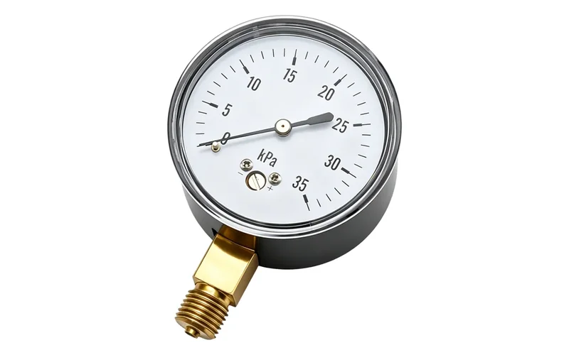
Uma linha de inertização com nitrogénio mantém 20 mbar em operação normal, e o regulador pode crívelmente fornecer 50 mbar em caso de falha. A carga é estável, pelo que 50 ÷ 0.75 = 66,7 mbar, que se arredonda para uma faixa de cápsula de 100 mbar. A pressão normal situa-se então em 20 ÷ 100 = 20% do span: a verificação do terço central falha.
A descida para a faixa padrão seguinte não resolve o problema. Uma faixa de 60 mbar colocaria o ponto de trabalho em 33%, mas 60 × 0.75 = 45 mbar está abaixo do máximo de 50 mbar, pelo que viola a recomendação de dimensionamento. Nenhuma faixa padrão satisfaz ambas as condições, porque a relação entre a pressão máxima e a normal é de 50 ÷ 20 = 2,5.
O cálculo está a dizer-lhe que a faixa não é a variável a ajustar. As opções são um limitador de pressão que limita o máximo para que uma faixa de 60 mbar se torne válida, ou aceitar a leitura na parte inferior da escala e recuperar a qualidade da medição com uma classe de exatidão mais rigorosa.
| Passo | Descarga de bomba | Unidade de potência hidráulica | Inertização com nitrogénio |
|---|---|---|---|
| Pnormal | 8 bar | 100 bar | 20 mbar |
| Pmax e origem | 12 bar, pressão de shut-off | 140 bar, ajuste de alívio | 50 mbar, falha do regulador |
| Tipo de carga e coeficiente | Estável, 0.75 | Pulsante, 0.65 | Estável, 0.75 |
| Mínimo calculado | 16,0 bar | 215,4 bar | 66,7 mbar |
| Faixa padrão encomendada | 16 bar | 250 bar | 100 mbar |
| Ponto de trabalho no mostrador | 50% ✓ | 40% ✓ | 20% × |
| Erro no ponto de trabalho, classe 1.6 | ±3,2% | ±4,0% | ±8,0% |
Quando o cálculo indica que um manômetro maior não ajuda
O terceiro exemplo generaliza. Antes do arredondamento, o ponto de trabalho é igual ao coeficiente multiplicado por Pnormal ÷ Pmax. Exigir que este atinja o piso de legibilidade de 33% limita a distância entre as duas pressões: Pmax ÷ Pnormal não deve exceder cerca de 2,3 para serviço estável (0.75 ÷ 0.33), ou cerca de 2,0 para serviço pulsante (0.65 ÷ 0.33). O arredondamento para cima baixa ainda mais o ponto de trabalho, pelo que esta é uma condição necessária, mas não suficiente.
Acima dessa proporção, nenhuma faixa satisfaz ambas as regras, e a resposta é reduzir Pmax em vez de aumentar a faixa: um amortecedor de pulsação para pulsação, um limitador de pressão para excursões, ou um manômetro digital com retenção de pico onde o próprio transiente deve ser capturado. A proteção contra sobrepressão é uma decisão de acessório, não uma decisão de mostrador.
Vale a pena separar dois valores que parecem contraditórios. A norma EN 837-1 estabelece limites de pressão para manômetros de Tubo de Bourdon como carga estável no valor de fundo de escala, carga flutuante a 0,9 vezes o fundo de escala e carga de curta duração a 1,3 vezes o fundo de escala, enquanto a EN 837-2 recomenda manter a carga máxima abaixo de 75%. A primeira descreve o que o instrumento suporta; a segunda é o que selecionar para vida útil, estabilidade do zero e legibilidade. A norma também distingue entre projetos carregáveis até o fundo de escala e não carregáveis até o fundo de escala, pelo que deve confirmar o limite para o modelo específico na sua folha de dados.
O que o cálculo da faixa não consegue decidir
Este procedimento dimensiona um mostrador. Não confirma os dados de entrada. Pmax, o meio, a temperatura e se a carga é genuinamente estável vêm todos do lado do processo, e uma faixa calculada a partir de um máximo otimista está errada, por mais cuidadosamente que seja arredondada.
Acertar na faixa também não completa a seleção. O material em contato com o processo, a ligação ao processo, o enchimento, o grau de proteção, o tamanho do mostrador e quaisquer requisitos de área classificada, serviço de oxigénio ou higiénicos são decisões separadas, e um manômetro com a faixa correta no material errado irá falhar na mesma.
Os ajustes de válvulas de alívio e as pressões de projeto pertencem à engenharia de processo e de equipamento: a seleção do manômetro lê esses números, nunca os altera. Para serviços relacionados com a segurança, peça ao engenheiro responsável que confirme a faixa, os pontos de ajuste dos acessórios e os materiais antes da libertação.
Pontos principais
- Dimensione a faixa a partir da pressão máxima crível dividida por 0.75 para carga estável ou 0.65 para carga pulsante e, em seguida, arredonde para uma faixa padrão.
- A exatidão é uma percentagem do span, pelo que uma faixa sobredimensionada multiplica o erro no ponto de trabalho em proporção direta.
- Se a pressão máxima exceder a pressão normal em mais de cerca de 2,3 vezes (2,0 para pulsante), nenhuma faixa satisfaz ambas as regras e a resposta é um acessório.
- O cálculo dimensiona apenas um mostrador: P_max, meio, temperatura e ajustes relacionados com a segurança devem ser confirmados pelo engenheiro de processo responsável.
Related buyer pages
Industrial pressure gauge manufacturerMatch the calculated working range to standard 0-1 to 0-1000 bar dial ranges before issuing an RFQ.
Custom pressure gauge manufacturerOrder non-standard ranges, dual-scale dials and psi/bar/MPa combinations when catalogue ranges do not fit.
Leituras relacionadas
- Requisitos do Manômetro para Sprinklers: UL 393 e NFPA 25
Requisitos do manômetro para sprinklers: por que a NFPA 13 exige manômetro listado UL 393 ou aprovado FM, como escolher faixa e escala, e as regras de substituição da NFPA 25.
- Classe de exatidão de manômetros: 4 variáveis-chave
Seleção da classe de exatidão de manômetros: que erro as classes EN 837-1 permitem, como span e ponto de trabalho mudam o erro real, e a classe por serviço.
- Seleção de vacuômetros: manômetros compostos e seus limites
Seleção de vacuômetros: as quatro referências de pressão, o elemento sensor de cada nível de vácuo e onde um mostrador mecânico deixa de servir.
- Seleção do manômetro da válvula de alívio: faixa e posição
Guia de seleção de manômetros para válvulas de alívio em vasos, skids de bombeamento, ar comprimido e caldeiras: faixa, margem sobre a pressão de ajuste, contrapressão, discos de ruptura e verificações de instalação segura.
Perguntas frequentes
Uma faixa de manômetro maior é mais segura?
Não. A exatidão é uma percentagem do fundo de escala, pelo que o sobredimensionamento multiplica o erro no seu ponto de trabalho. Um manômetro de classe 1.6 a ler 100 bar dá ±2,6% da leitura numa faixa de 160 bar, mas ±6,4% numa faixa de 400 bar. A proteção contra picos pertence a amortecedores e limitadores, não a um mostrador maior.
Por que um manômetro de 400 bar é inexato a 100 bar?
Classe 1.6 significa ±1,6% do span de 400 bar, o que equivale a ±6,4 bar em qualquer ponto do mostrador. Numa leitura de 100 bar, esse valor fixo de ±6,4 bar corresponde a ±6,4% do valor lido, enquanto o mesmo erro absoluto a 250 bar seria de apenas ±2,6%.
A regra dos 75% é um requisito da norma?
É uma recomendação, não um requisito. A norma EN 837-2, a parte da norma sobre seleção e instalação, recomenda que a carga de pressão máxima se mantenha abaixo de 75% do fundo de escala sob carga estável e 65% sob carga flutuante. Aplica-se à carga máxima, não à pressão normal de operação.
E se a faixa calculada não for uma faixa padrão?
Arredonde para a faixa seguinte na série decimal 1, 1.6, 2.5, 4, 6 e, em seguida, repita a verificação na faixa que irá encomendar. O arredondamento para cima baixa o ponto de trabalho e aumenta o erro nesse ponto na mesma proporção.
Como calculo a faixa para um manovacuômetro ou vacuômetro?
Use os mesmos coeficientes, mas baseie a verificação do ponto de trabalho no span total. Um mostrador de -1 a 0 a 15 bar tem um span de 16 bar, pelo que uma pressão de trabalho de 5 bar situa-se em 6 bar do span, ou 37,5%, e não a um terço da secção positiva.
Como converto uma faixa em bar para psi ao comparar catálogos?
Multiplique por 14.5038. Uma faixa de 16 bar equivale a 232 psi e 250 bar a 3626 psi, razão pela qual as faixas em psi nos catálogos parecem irregulares: são conversões da série em bar. 1 bar também equivale a 0.1 MPa, 100 kPa e 1.0197 kgf/cm².