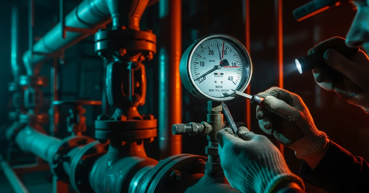
Industrial pressure gauges are critical for process control and safety, yet they are susceptible to various failure modes that compromise accuracy and reliability. This guide provides a systematic pressure gauge failure troubleshooting methodology, addressing common issues encountered in industrial service. We will explore root causes, diagnostic steps, and preventative measures for problems ranging from mechanical failures like a stuck pointer to environmental challenges such as internal fogging and fill-fluid leakage. Understanding these failure mechanisms is essential for B2B distributors, OEM equipment makers, and plant engineers to ensure optimal instrument performance and extend service life, aligning with standards like EN 837-1 and ASME B40.100.
Failure Mode 1-2: Pointer Stuck or Off-Scale
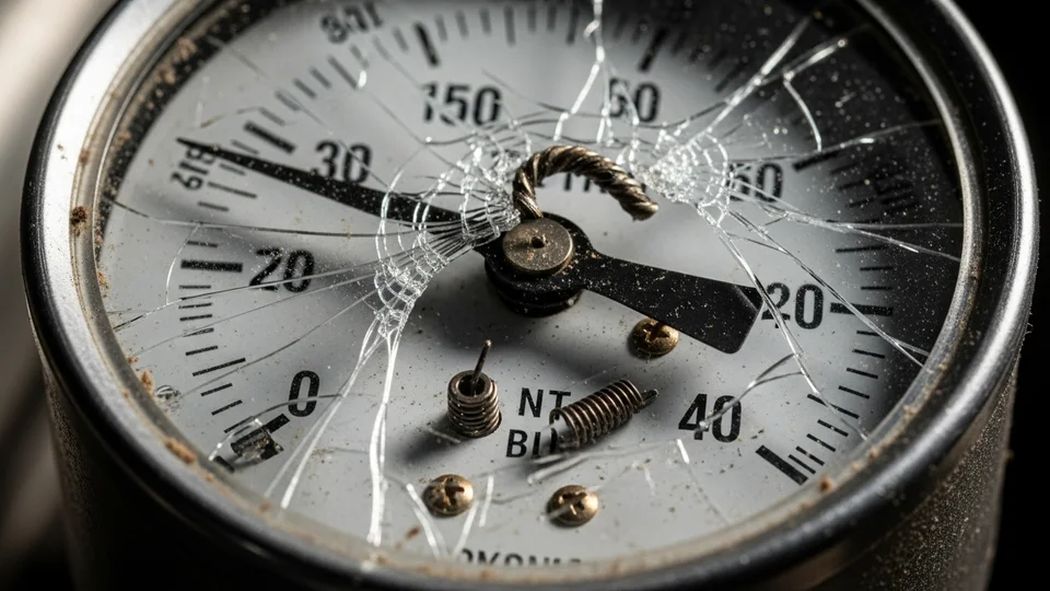
When a pressure gauge pointer is stuck at zero or any fixed position, common root causes include a blocked orifice, a seized Bourdon tube, or a broken movement. A blocked orifice, often due to process media particulate or crystallization, prevents pressure transmission to the Bourdon tube. To diagnose, isolate the gauge and check for flow through the connection. A seized Bourdon tube, typically from corrosion or mechanical stress, will prevent the tube from flexing. This can be identified by applying a known pressure source; if the pointer remains static, the tube is likely seized. A broken movement, involving gears or linkages, results in a disconnected pointer. Visual inspection of the internal mechanism, often requiring removal of the window, can confirm this.
Conversely, a pointer that is off-scale or exhibits no return to zero after pressure release usually indicates an over-pressure event that has caused the Bourdon tube to yield. This permanent deformation means the tube has exceeded its elastic limit. Gauges are designed for a maximum operating pressure of 75% of full scale, with intermittent peaks up to 100%. Exceeding 125% of the full-scale range typically causes permanent damage. For example, a 100 psi gauge exposed to 150 psi will likely yield.
To troubleshoot, first verify the process pressure did not exceed the gauge's maximum rating. If an over-pressure event is confirmed, the Bourdon tube is compromised, and the gauge requires replacement. Adherence to ASME B40.100 guidelines for over-pressure protection, such as installing a pressure limiter or using a higher-range gauge, is crucial. Regular calibration checks can also reveal early signs of Bourdon tube fatigue or zero shift, indicating potential yielding.
| Failure Symptom | Root Cause | Diagnostic Action | Corrective Action |
|---|---|---|---|
| Pointer stuck at zero | Blocked orifice | Isolate, check for flow | Clean or replace orifice |
| Pointer stuck at zero | Seized Bourdon tube | Apply known pressure, observe pointer | Replace gauge |
| Pointer stuck at zero | Broken movement | Visual inspection of internal mechanism | Replace gauge |
| Pointer off-scale | Over-pressure event | Verify process pressure history | Replace gauge, implement over-pressure protection |
For standard requirements, compare symptoms with EN 837-1 pressure gauge service criteria and ASME B40.100 pressure gauge guidance.
Browse Our Pressure Gauge Catalog →Explore 143+ industrial gauge models→Failure Mode 3-4: Fogging, Condensation, and Fill-Fluid Leakage
Internal fogging or condensation within a pressure gauge is a common issue, primarily caused by temperature cycling or a cracked window seal. Temperature fluctuations cause air inside the gauge case to expand and contract, drawing in moist ambient air if seals are compromised. When the temperature drops, this moisture condenses on the cooler internal surfaces, including the window. A cracked window seal directly allows moisture ingress. Liquid-filled gauges, while mitigating condensation on the dial face, can still experience it on the inside of the window if the case is not properly sealed. Inspect the window gasket and case integrity for any visible cracks or gaps.
Glycerin leakage, a characteristic issue for liquid-filled gauges, typically points to a case seal failure or thermal expansion exceeding the gauge's design limits. Liquid-filled gauges use a fill fluid (commonly glycerin or silicone) to dampen pulsations and vibrations, lubricate internal components, and prevent condensation. A compromised case seal, often due to aging, chemical attack, or physical damage, allows the fill fluid to escape. This is usually visible as a greasy residue on the exterior of the gauge or surrounding equipment.
Thermal expansion of the fill fluid can also cause leakage if the gauge is not equipped with a proper pressure-compensating diaphragm or if it's exposed to temperatures significantly above its rated range. For example, a gauge filled with glycerin (operating range typically -20°C to +60°C) exposed to 80°C might experience fluid expansion leading to seal stress and leakage. Manogauge designs incorporate robust case seals and, for specific applications, pressure-compensating features to mitigate these issues, compliant with EN 837-1.
To troubleshoot, first check for visible signs of damage to the case or window seal. If fogging persists despite intact seals, consider gauges with a higher ingress protection (IP) rating or those designed for extreme temperature variations. For glycerin leakage, identify the source of the leak – often around the fill plug, window seal, or process connection. If the leak is minor and the gauge is still functional, a seal replacement might be possible, but often, replacement of the entire gauge is more cost-effective, especially if the internal components have been exposed to contaminants or air bubbles have formed within the fill fluid, impacting dampening performance.
Vibration-related pointer damage often points back to dry vs. liquid-filled pressure gauges for vibration environments.
Failure Mode 5-6: Zero Drift and Sluggish Response
Zero drift after installation is a common issue, often indicative of mechanical shock or process pulsation fatigue. Mechanical shock, such as dropping the gauge or subjecting it to excessive vibration during transport or installation, can misalign the movement or deform the Bourdon tube, leading to a permanent zero shift. Even minor impacts can affect the delicate linkage system. Process pulsations, common in pump discharge lines or reciprocating compressor systems, subject the Bourdon tube and movement to rapid, repetitive stress cycles. Over time, this fatigue can cause the Bourdon tube to lose its elastic properties, resulting in a gradual upward or downward zero shift. This is particularly prevalent if the gauge is not liquid-filled or protected by a snubber.
To diagnose, first verify the gauge was installed correctly and not subjected to undue force. If zero drift occurs over time, consider the process environment. If pulsations are suspected, compare the gauge's zero reading after isolation from the process to its initial factory zero. A consistent deviation indicates permanent damage. Manogauge recommends liquid-filled gauges or the use of external dampeners (snubbers) for applications with significant pulsation, adhering to ASME B40.100 guidelines for pulsation protection.
Reading lag or sluggish response means the gauge pointer takes an unusually long time to settle at the correct pressure, or it fails to respond quickly to pressure changes. The primary causes are a snubber that is too restrictive or the use of a high-viscosity fill fluid in cold environments. Snubbers are designed to dampen pulsations but if the orifice size is too small for the application, it can impede pressure transmission, causing a delayed response. This is often observed when a gauge responds slowly to a rapid pressure drop or increase.
High-viscosity fill fluids, such as silicone oil used in extremely low-temperature applications, can become even more viscous in colder ambient conditions, increasing drag on the Bourdon tube and movement. While beneficial for dampening, excessive viscosity can hinder the pointer's ability to move freely. To troubleshoot, first check the snubber. If adjustable, try opening it slightly. If fixed, consider a snubber with a larger orifice. For fill-fluid issues, ensure the gauge's fill fluid is appropriate for the operating temperature range. For example, glycerin is suitable for -20°C to +60°C, while silicone oil extends to -40°C or lower. If the wrong fluid is used, the gauge may need replacement with one filled with a lower-viscosity fluid suitable for the specific temperature range.
Corrosion failures should be matched against 316L stainless steel vs. brass corrosion resistance.
Request a Free QuoteOur engineers respond within 24 hours→Failure Mode 7: Corrosion-Induced Measurement Error
Corrosion-induced measurement error is a critical failure mode, directly impacting accuracy and potentially leading to catastrophic failures. The root cause is invariably the wrong wetted material for the process fluid. Pressure gauges come with various wetted parts materials, such as brass, 316L stainless steel, Monel, or Hastelloy. If the material chosen for the Bourdon tube, socket, or other parts in contact with the process fluid is not chemically compatible, it will corrode. Corrosion can manifest as pitting, thinning, or embrittlement of the Bourdon tube, leading to a compromised elastic response and inaccurate readings. In severe cases, it can cause the Bourdon tube to rupture, releasing process fluid.
For example, a brass wetted gauge exposed to ammonia or strong acids will quickly corrode, leading to premature failure. Even 316L stainless steel, while highly resistant, can be susceptible to pitting corrosion in chloride-rich environments or crevice corrosion. The rate and type of corrosion depend on the specific chemical composition, concentration, temperature, and pressure of the process fluid. EN 837-1 and ASME B40.100 standards emphasize the importance of material compatibility for safety and performance.
To troubleshoot, review the material safety data sheet (MSDS) of the process fluid and compare it against the wetted materials of the installed gauge. Any discrepancy indicates a high probability of corrosion. Visual inspection of the gauge's wetted parts (if safe to do so after depressurizing and isolating) may reveal signs of corrosion. If corrosion is evident, the gauge must be replaced immediately. The corrective action involves selecting a gauge with wetted materials specifically rated for the process fluid. For highly corrosive or aggressive media, consider using a diaphragm seal assembly, which isolates the gauge from the process fluid using a compatible diaphragm and fill fluid. This provides an additional layer of protection and extends the gauge's service life in challenging applications. Always consult chemical compatibility charts or Manogauge's technical support when selecting wetted materials for new installations or when process fluid characteristics change.
Many zero and readability issues start with installation; review pressure gauge installation best practices.
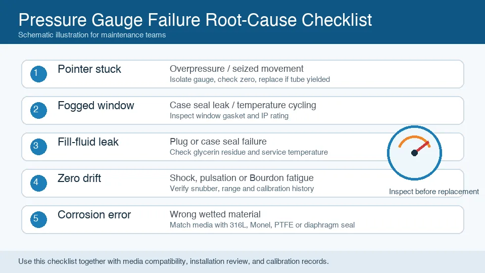
Root-Cause Checklist and Service-Life Indicators
A systematic root-cause checklist is invaluable for efficient pressure gauge failure troubleshooting. Begin by verifying the process conditions: Is the pressure within the gauge's rated range (75% of full scale for continuous operation)? Are there significant pulsations or temperature fluctuations? Next, inspect the gauge externally: Check for physical damage, leaks (fill fluid or process fluid), and the integrity of seals and connections. Observe the pointer's behavior: Is it stuck, sluggish, or showing an incorrect zero? Finally, consider the installation environment: Is the gauge exposed to excessive vibration, corrosive atmosphere, or extreme temperatures?
| Checklist Item | Observation | Potential Root Cause |
|---|---|---|
| Process Pressure | Exceeds 75% of FS, or over 125% peak | Over-pressure, Bourdon tube yield |
| Process Pulsation | Visible pointer oscillation | Fatigue, zero drift, snubber needed |
| Temperature Range | Outside gauge's rated limits | Fogging, fill-fluid viscosity issues, seal degradation |
| External Damage | Cracks, dents, leaks | Mechanical shock, seal failure |
| Wetted Materials | Incompatible with process fluid | Corrosion, premature failure |
Service-life indicators provide proactive insights into a gauge's remaining operational lifespan. Regular calibration is the most critical indicator; a gauge that consistently fails calibration or exhibits increasing zero shift or non-linearity is nearing the end of its service life. For example, if a gauge's error exceeds ±1.0% of full scale (Grade 1A per ASME B40.100) during calibration, it should be replaced. Visible signs of wear, such as a faded dial, corroded case, or a yellowing fill fluid (for glycerin-filled gauges), also suggest aging. A gauge that frequently requires recalibration or exhibits intermittent issues is a strong candidate for replacement. Manogauge recommends a calibration interval of 6-12 months, depending on the criticality and severity of the application. Proactive replacement based on these indicators can prevent unexpected failures, minimize downtime, and maintain process integrity, ensuring compliance with industry standards like GB/T 1226-2017.
When replacement is needed, restart specification from the industrial pressure gauge selection guide.
Key takeaways
- Always select pressure gauges with wetted materials compatible with the process fluid to prevent corrosion and ensure safety.
- Utilize liquid-filled gauges or external snubbers in applications with significant pulsations or vibration to extend service life and maintain accuracy.
- Regularly calibrate pressure gauges (every 6-12 months) and replace those exhibiting persistent zero drift or exceeding accuracy tolerances.
- Inspect gauge seals and connections for integrity to prevent internal fogging, condensation, and fill-fluid leakage, especially in environments with temperature cycling.
- Ensure the gauge's operating range is appropriate for the process, ideally with continuous pressure below 75% of full scale, to avoid over-pressure damage.
Related products
- Isolating-Diaphragm Gauge - Radial Type 1 (ZX-04-R1) — 0–60 MPa
- Shock-Resistant Pressure Gauge - Radial (ZX-03-R) — 0–270 psi
Frequently asked questions
Why does my pressure gauge pointer get stuck at zero?
A pointer stuck at zero often indicates a blocked orifice, preventing pressure transmission, a seized Bourdon tube due to corrosion or stress, or a broken internal movement. Isolate the gauge and check for flow, or inspect the internal mechanism for damage.
What causes internal fogging in a pressure gauge?
Internal fogging or condensation is typically caused by temperature cycling, which draws moist air into the gauge case through compromised seals, or a cracked window seal allowing direct moisture ingress. Inspect seals and consider a higher IP-rated gauge.
How can I prevent glycerin leakage from my liquid-filled gauge?
Glycerin leakage usually results from case seal failure or excessive thermal expansion. Ensure the gauge's temperature rating is suitable for the application and inspect seals for damage. Use gauges with pressure-compensating diaphragms for high temperatures.
Why does my pressure gauge show zero drift after installation?
Zero drift often stems from mechanical shock during installation or fatigue from process pulsations. Ensure careful handling and consider liquid-filled gauges or snubbers for pulsating applications to protect the Bourdon tube and movement.
What is the best way to troubleshoot a sluggish pressure gauge response?
Sluggish response is usually due to an overly restrictive snubber or high-viscosity fill fluid in cold conditions. Check the snubber's orifice size and ensure the fill fluid's viscosity is appropriate for the operating temperature range.