In industrial production, pressure gauges are among the most widely used process instruments, found on nearly every pipeline and piece of equipment. However, selecting the correct model for specific operating conditions from hundreds of options remains a significant challenge for many engineers and procurement personnel. The cost of selection errors extends far beyond the instrument's price – incorrect wetted parts can lead to rapid corrosion and media leaks, an unsuitable range can damage the measuring mechanism, and neglecting vibration factors can render a gauge completely inoperable within weeks. This article provides a systematic 7-step selection framework, covering all critical dimensions of pressure gauge selection, from operating pressure range and process media characteristics to installation environment and essential safety accessories. It aims to help engineers find the optimal solution in minutes and effectively avoid common selection pitfalls.
Step 1: Determine Operating Pressure Range and Gauge Span
Selecting the gauge span is the first and most critical step in pressure gauge selection. The core principle is the 75% Rule: Under normal operating conditions, the working pressure should fall within 25% to 75% of the instrument's full scale. This principle is explicitly stipulated in both major standards: EN 837-1 and ASME B40.100.
Why 75%? When elastic measuring elements (Bourdon tubes) are subjected to pressures exceeding 75% of the span for extended periods, they can experience fatigue creep, leading to zero shift and reduced accuracy. Conversely, operating below 25% of the span means readings are in the lowest section of the dial, resulting in poor resolution and an amplified relative error.
| Operating Condition | Recommended Operating Pressure Range |
|---|---|
| Stable Static Pressure (Ideal Conditions) | 25% to 75% of Full Scale |
| Slight Pulsation Present | 25% to 65% of Full Scale |
| Frequent Pulsation (Pump, Compressor Outlet) | 25% to 50% of Full Scale |
| Risk of Overpressure | Select span so peak pressure does not exceed full scale |
Common Standard Spans (EN 837-1): 0.6 / 1 / 1.6 / 2.5 / 4 / 6 / 10 / 16 / 25 / 40 / 60 / 100 / 160 / 250 / 400 / 600 bar. When selecting, round up to the nearest standard span. The optimal choice is to ensure the normal operating pressure falls approximately within 40% to 60% of the selected span.
For standards context, compare the range rule with ASME B40.100 pressure gauges and gauge attachments and EN 837-1 Bourdon tube pressure gauges.
Browse Our Pressure Gauge Catalog →Explore 143+ industrial gauge models→Step 2: Analyze Process Media and Select Wetted Parts Material
The "wetted parts" of a pressure gauge refer to the components that come into direct contact with the process media. These primarily include the Bourdon tube, process connection, and (if applicable) the diaphragm. Incorrect material selection can lead to minor issues like reading drift, or severe consequences such as media leakage and safety incidents.
Brass (CuZn): The most cost-effective option, suitable for water, air, inert gases, petroleum-based hydraulic oils, and mild chemicals. Prohibited for use with ammonia (NH₃), acetylene (C₂H₂), or any media where copper ions can trigger catalytic reactions.
316L Stainless Steel (SS316L): Offers significantly better corrosion resistance than brass, making it suitable for dilute acids, dilute alkalis, saltwater, food and beverage applications, and water treatment. Its Pitting Resistance Equivalent Number (PREN≈25) allows it to resist moderately concentrated chloride environments. For high-chloride environments, an upgrade to duplex stainless steel or Hastelloy C-276 is required.
Special Media Considerations:
- Oxygen Systems: Must use oil-free/grease-free dedicated instruments to prevent ignition or deflagration upon contact with oxygen.
- Acetylene Systems: Prohibit wetted parts made of copper or copper alloys (copper content >65% can form explosive copper acetylide).
- High Viscosity or Media with Solid Particles: Diaphragm pressure gauges or chemical seals (diaphragm seals) should be selected to prevent media from entering and clogging the measuring chamber.
When dealing with highly corrosive media and material suitability is uncertain, consult NACE corrosion data sheets or contact the instrument manufacturer for compatibility confirmation.
For deeper material decisions, see our 316L stainless steel vs. brass wetted parts guide.
Step 3: Selecting the Measuring Element Type
The measuring element is the core of a pressure gauge, with different types suited for various pressure ranges and media characteristics.
Bourdon Tubes are the most common measuring elements in industrial applications, covering a wide range from 0.6 bar to 6000 bar. They are robust and cost-effective. Standard C-type Bourdon tubes are suitable for most applications; helical Bourdon tubes are used for ultra-high pressures (>400 bar); and spiral types are used for high-precision measurements.
Diaphragm Elements are suitable for low to medium pressure ranges from 0 to 40 bar. They are particularly well-suited for viscous media, slurries containing solid particles, or corrosive media, as the absence of narrow channels between the diaphragm and the process medium prevents clogging. Diaphragm materials include 316L SS, Hastelloy, Tantalum, etc.
Capsule Elements are specifically designed for very low pressure and differential pressure measurements (0 to 600 mbar). They are ideal for applications such as furnace pressure, ventilation duct static pressure, and gas filter differential pressure, offering superior accuracy compared to Bourdon tubes in the same range.
| Element Type | Applicable Range | Typical Applications |
|---|---|---|
| Bourdon Tube (C-type) | 0.6 to 600 bar | General industrial pressure measurement |
| Bourdon Tube (Helical) | 400 to 6000 bar | High-pressure hydraulics, ultra-high pressure processes |
| Diaphragm Element | 0 to 40 bar | Corrosive, viscous, slurry media |
| Capsule Element | 0 to 600 mbar | Very low pressure, differential pressure, gas filters |
If the application sits near the boundary between sensing technologies, review Bourdon tube vs. diaphragm sensing elements.
Request a Free QuoteOur engineers respond within 24 hours→Step 4: Determining Accuracy Class and Dial Size
Accuracy Class determines the reliability of measurement results and should be selected based on process control requirements, rather than the principle of 'the more precise, the better'.
Accuracy classes defined by EN 837-1 (expressed as a percentage of full scale): 4.0 → 2.5 → 1.6 → 1.0 → 0.6 → 0.25 (lower values indicate higher accuracy).
- 4.0% / 2.5%: For rough on-site monitoring, not involving precise control, such as pipeline pressure surveillance or equipment operational status indication.
- 1.6% / 1.0%: Standard accuracy for industrial process control, suitable for most chemical, mechanical, and municipal water applications.
- 0.6% / 0.25%: For precision measurement, calibration reference, safety-critical instrumentation, and pharmaceutical cleanrooms, requiring strict calibration management.
Dial Size affects reading resolution and on-site readability:
- 63mm: Control panels, small equipment, space-constrained applications.
- 100mm: Preferred industrial standard, balancing readability and cost-effectiveness.
- 160mm / 250mm: For field inspections, long-distance reading, and precision applications requiring high resolution.
Tip: A larger dial allows for finer scale divisions, reducing on-site reading errors and often providing better practical readability than the instrument's nominal accuracy class.
Accuracy decisions should also reference our pressure gauge accuracy class guide.
Step 5: Determine Mounting Style and Connection Specifications
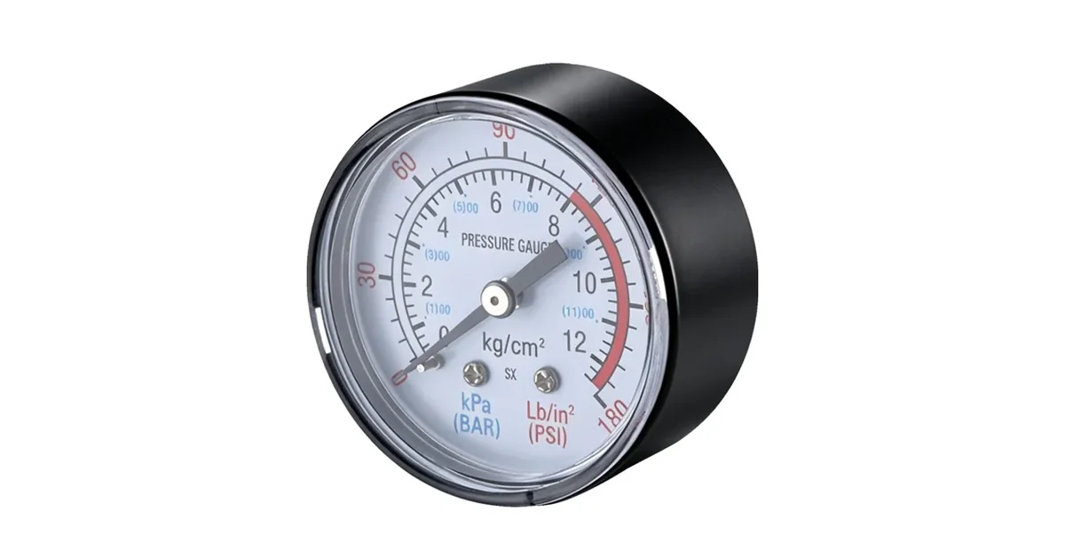
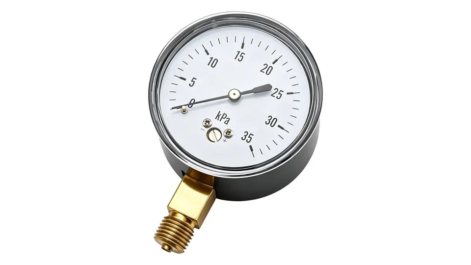
Mounting orientation is divided into radial (Lower Mount / L-type) and axial (Back Mount / U-type). Lower mount is suitable for direct pipe connection, while back mount is ideal for panel or wall mounting. Bourdon tube pressure gauges should ideally be installed with the connection facing downwards to prevent liquid accumulation in the measuring chamber from affecting readings.
Connection thread specifications are one of the most common sources of error for engineers globally when selecting instruments:
| Thread Type | Sealing Method | Primary Application Regions |
|---|---|---|
| NPT (National Pipe Taper) | Thread profile self-seal + PTFE tape | North America, parts of Asia |
| BSPT / Rc (British Standard Pipe Taper) | Thread profile self-seal + PTFE tape | Europe, China, Southeast Asia |
| G / BSPP (British Standard Pipe Parallel) | Combination seal washer (O-ring + metal backing) | European hydraulic systems |
| Metric M20×1.5 | Metal face seal or O-ring | Germany / European industrial |
Common Error: NPT and BSPT threads are visually very similar, but their taper angles and pitches differ slightly (NPT 1:16, BSPT 1:16 but thread angle 55° vs 60°). Forcibly interchanging them will lead to poor sealing or thread damage. Always confirm the existing piping system's thread standard before ordering.
For thread and sealing details, use the NPT, BSP and metric thread connection guide.
Step 6: Evaluate Operating Environment, Select Case Type and Protection Rating
The operating environment is crucial for the long-term reliability of the instrument. The following four dimensions must be evaluated:
1. Mechanical Vibration and Pressure Pulsation Continuous vibration and pressure pulsations in pump outlets, compressor pipelines, and piping near vibrating equipment can cause the pointer of dry pressure gauges to oscillate violently, eventually leading to movement damage. Solution: Select liquid-filled pressure gauges (glycerin filling suitable for -20°C to +60°C; silicone oil filling suitable for -40°C to +70°C), or install a snubber at the connection.
2. Ambient Temperature Standard pressure gauges typically operate within an ambient temperature range of -20°C to +65°C. For outdoor low-temperature environments, silicone oil-filled gauges or instruments with heating devices should be selected. For high-temperature process media (>60°C), a siphon (coil siphon or pigtail siphon) must be installed to prevent hot steam from directly entering the Bourdon tube.
3. Ingress Protection (IP Rating)
- IP54: Dust protected and splash-proof, suitable for general industrial workshops
- IP65: Dust-tight + jet-proof, suitable for outdoor and washdown environments
- IP67: Protected against temporary immersion, suitable for food and beverage, cleanrooms
- IP69K: Resistant to high-pressure hot water washdown, preferred for dairy and pharmaceutical CIP/SIP applications
4. Hazardous (Explosive) Areas In areas with flammable gases or dusts, ATEX / IECEx certified explosion-proof instruments must be selected. The appropriate explosion protection category (e.g., ia/ib/d) should be chosen according to the hazardous area classification (Zone 0/1/2 or Zone 20/21/22).
Step 7: Specifying Safety Accessories and Instrument Protection Devices
Even a correctly selected pressure gauge may require accessories to operate safely and reliably under specific conditions:
Snubber / Pulsation Dampener: Installed upstream of the pressure gauge connection, it reduces the impact of pressure pulsations on the gauge movement through a porous sintered element or an adjustable orifice. Available in fixed-orifice and adjustable types, common materials include brass and stainless steel. The material must be compatible with the wetted parts of the instrument.
Diaphragm Seal / Chemical Seal: Completely isolates the process medium from the pressure gauge. Suitable for highly corrosive media, high-viscosity or media containing solid particles, extremely high/low temperature media, and food/pharmaceutical processes requiring hygienic cleanliness. The sealed chamber is filled with a pressure-transmitting fluid (e.g., silicone oil) to indirectly transmit pressure to the instrument.
Root Valve: Installed between the instrument and the process pipeline, it allows for instrument removal and installation without shutting down the process. It is recommended that all pressure gauges on production lines be equipped with a root valve.
Siphon Tube / Steam Coil: Used in steam lines. The coil is filled with condensate, forming a liquid column that acts as a thermal barrier, preventing high-temperature steam from directly entering the Bourdon tube, which could lead to range drift or movement damage.
Conclusion: Establishing a Standardized Selection Checklist
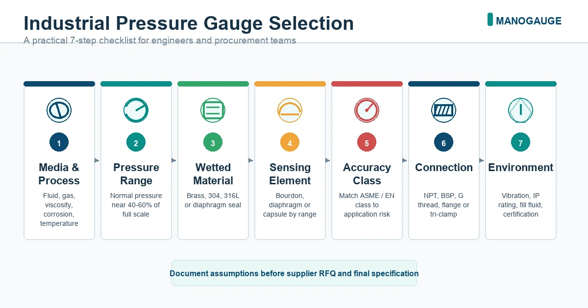
A systematic selection process not only enhances instrument reliability but also significantly reduces maintenance costs and unplanned downtime losses. We recommend that factories and engineering companies compile the above 7 steps into a standardized Instrument Data Sheet, checking each item before every purchase:
✅ Operating Pressure Range and Span (75% Rule) ✅ Process Medium Chemical Properties and Wetted Part Material Compatibility ✅ Measuring Element Type (Bourdon Tube / Diaphragm / Capsule) ✅ Accuracy Class and Dial Size ✅ Mounting Type and Process Connection Thread Standard ✅ Ambient Temperature, Vibration, and Ingress Protection (IP) Rating Requirements ✅ Required Safety Accessories (Snubber / Seal / Root Valve)
To receive a quick quote based on these parameters, please contact the Manogauge technical team. We will respond to your selection inquiry within 24 hours.
Frequently Asked Questions (FAQ)
Q1: How should the pressure gauge range be selected? Can it be exactly equal to the maximum operating pressure?
Not recommended. The pressure gauge range should be selected so that the normal operating pressure falls within 25% to 75% of the full scale. If the normal operating pressure is 6 bar, a 10 bar range should be chosen, not a 6 bar range. This ensures both measurement accuracy within the optimal range and sufficient overpressure protection margin.
Q2: Under what circumstances is a liquid-filled pressure gauge mandatory?
A liquid-filled gauge should be selected when any of the following conditions exist at the installation location: ① Continuous mechanical vibration caused by equipment such as pumps or compressors; ② Frequent process pressure pulsations (e.g., at the outlet of a piston pump); ③ The instrument is installed on mobile equipment (e.g., construction machinery, marine vessels). Liquid filling effectively dampens vibrations, lubricates the movement gears, and extends service life.
Q3: Is a stainless steel pressure gauge suitable for all corrosive media?
No. While 316L stainless steel resists most dilute acids, alkalis, and salt solutions, it will still corrode rapidly in the presence of highly corrosive media such as concentrated hydrochloric acid or hydrofluoric acid. For high-chloride environments (>1000 ppm Cl⁻), Hastelloy C-276 or titanium should be considered; for strong oxidizing acids (e.g., concentrated nitric acid), tantalum wetted parts should be considered.
Q4: Is there a significant difference between accuracy classes 1.6% and 0.6% in practical applications?
For an instrument with a 100 bar range, the maximum permissible error for 1.6% accuracy is ±1.6 bar, while for 0.6% accuracy, it is ±0.6 bar. In applications requiring precise flow control or accurate reactor pressure regulation, this difference directly impacts product quality. However, for general pipeline monitoring, 1.6% accuracy is entirely sufficient, and the cost is significantly lower than higher accuracy class instruments.
Q5: How do I determine if a chemical seal (diaphragm seal) is required?
A chemical seal should be considered in the following situations: ① The process medium is highly corrosive to available wetted materials, with no suitable metallic options; ② The medium has high viscosity or contains solid particles that could clog the Bourdon tube inlet; ③ The medium solidifies or crystallizes at ambient temperatures (e.g., certain high-melting-point organic substances); ④ Hygienic cleanliness is required, necessitating the elimination of dead spaces (food, pharmaceutical industries). Adding a chemical seal introduces additional system lag and temperature errors, which must be carefully weighed during selection.
Key takeaways
- Range selection follows the 75% rule: normal operating pressure should be between 25% and 75% of the full scale, and not exceed 50% under pulsating conditions.
- Wetted parts material must be chosen based on the process media's corrosivity, temperature, and specific requirements (e.g., oil-free for oxygen service), not merely by selecting the most expensive option.
- For any installation location with continuous vibration or pressure pulsation, liquid-filled pressure gauges are mandatory; otherwise, instrument lifespan will be significantly reduced.
- Safety accessories (snubbers, chemical seals, siphons, and root valves) are crucial for ensuring system reliability and should not be considered optional or omitted.
- Connection thread standards (NPT, BSPT, G) must precisely match existing piping standards; forcing different thread types together will lead to seal failure.
Related products
- General Pressure Gauge - Radial (ZX-08-R) — 0–40 MPa
- Stainless Steel Pressure Gauge - Radial (ZX-01-R) — 0–100 MPa
- Liquid-Filled Pressure Gauge - Radial (ZX-06-R) — 0–60 MPa
Frequently asked questions
What are the key parameters for selecting an industrial pressure gauge?
The 7-step selection framework: (1) Pressure range — select 1.25–1.5× maximum working pressure as full scale; (2) Accuracy class — 1.6 for monitoring, 0.6 for control loops; (3) Process medium — determine wetted material requirements (brass for dry air, 316L SS for corrosive/food, Hastelloy for aggressive chemicals); (4) Fill type — dry for stable environments, liquid-fill for vibration/pulsation; (5) Dial size — 63mm for space-constrained, 100mm standard, 160mm for remote reading; (6) Connection — specify size AND type (NPT, BSPP, BSPT, metric); (7) Environment — IP rating, ATEX zone, temperature range.
What process media require stainless steel wetted parts?
Specify 316L stainless steel wetted parts for: salt water and marine environments, food and beverage processes, mild chemical service (pH 4–10 with no chloride), steam and condensate systems, hydraulic oil (if chemical compatibility is confirmed), and CO₂/refrigerant systems. Brass wetted parts are acceptable ONLY for compressed air, inert gases, and clean water below 60°C — never for corrosive chemicals, seawater, or food contact applications.
What does 'wetted parts' mean for a pressure gauge?
Wetted parts are all gauge components that contact the process medium: the Bourdon tube, the socket (connection body), the socket threads, and any O-rings or seals in the process connection. The case, movement, and dial are not wetted parts and do not require process compatibility. When specifying material for corrosive service, you only need to upgrade the wetted parts, not the entire gauge.
How do I specify a pressure gauge for outdoor installation?
Outdoor installations require: IP65 minimum case protection (EN 60529) for dust and rain; UV-stable case material (ABS or stainless steel — avoid polycarbonate in direct sunlight); operating temperature range covering site minimum (arctic: −40 °C, temperate: −20 °C) and maximum; liquid fill to prevent condensation in the case; and anti-corrosion coating or all-stainless construction in coastal or industrial atmospheres.
What certifications should I require for pressure gauges in a regulated facility?
Standard industrial: CE marking (EU, PED compliance); ISO 9001 (manufacturing quality). Application-specific: ATEX/IECEx (explosive atmospheres); 3-A or EHEDG (food/dairy); FDA 21 CFR (pharmaceutical); KS (Korea); CRN (Canada); INMETRO (Brazil). For safety instrumented systems, verify the gauge can meet the proof-test interval and PFD requirements of the target SIL level. Request the Declaration of Conformity and test certificates for each required standard.
What is the difference between gauge pressure, absolute pressure, and differential pressure measurement?
Gauge pressure (G or PSIG): measures pressure relative to atmospheric pressure — the most common type for industrial processes. Absolute pressure (A or PSIA): measures pressure relative to perfect vacuum — required for gas density calculations, boiling point determination, and vacuum system monitoring. Differential pressure (DP): measures the difference between two pressures — used for flow measurement (orifice plates), filter ΔP monitoring, and level measurement by pressure difference. Specify the measurement type explicitly, as gauges are not interchangeable between types.