Compressed air pressure monitoring is the planned measurement of pressure and differential pressure from compressor discharge to the most demanding end use. A pressure profile separates supply problems, treatment losses, distribution restrictions and local regulator issues instead of treating every low-pressure complaint as a reason to raise compressor setpoint.
What compressed air pressure monitoring should prove
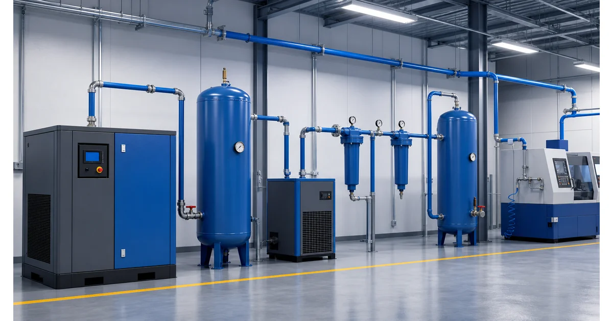
Compressed air pressure monitoring is a system-level method, not a single gauge beside a compressor. The objective is to establish a pressure profile: a time-aligned set of readings at compressor discharge, wet receiver, dryer and filter outlet, dry receiver, main header, remote branch and critical end use. The profile shows where pressure is lost and whether the loss is constant or demand-dependent.
The U.S. Department of Energy defines pressure drop as the reduction from compressor discharge to the actual point of use and recommends a pressure profile to identify system problems in its compressed air system analysis guidance. This distinction matters because raising the compressor setpoint may hide a restriction while increasing power demand, leakage and artificial demand.
The primary keyword is compressed air pressure monitoring. Supporting terms are compressed air pressure drop, air compressor pressure gauge and filter differential pressure. Related Manogauge references include pressure transmitter vs pressure gauge selection and pressure gauge installation best practices.
Review Industrial Pressure Gauge Options →Explore 143+ industrial gauge models→Where to measure pressure in a compressed air system
Measurement points should correspond to decisions. A gauge that cannot distinguish compressor control behavior from filter restriction has limited diagnostic value. Record operating state, flow or compressor loading with the pressure values whenever possible.
| Measurement point | Preferred instrument | Diagnostic purpose |
|---|---|---|
| Compressor discharge | Transmitter plus local gauge | Control band, loading cycle, abnormal discharge pressure |
| Wet receiver outlet | Local gauge | Supply stability and separation from short compressor cycles |
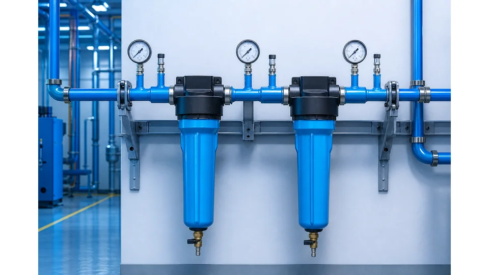
| Across dryer and filters | Differential transmitter or paired taps | Treatment pressure loss, blocked element, maintenance timing |
| Dry receiver / main header | Transmitter | Plant supply pressure and demand events |
| Remote branch | Gauge or data logger | Undersized piping, closed valve, branch restriction |
| Critical machine inlet | Local gauge near regulator | Pressure actually available during the production cycle |
A single reading taken during low production can miss the problem. Trend the high-demand shift, machine actuation cycles and compressor transitions. A pressure drop that grows with flow usually indicates restriction; a stable offset may indicate regulator setting, elevation, calibration mismatch or a partially closed valve.
Diagnosing compressed air pressure drop across filters and dryers
Filters, dryers, separators, check valves and treatment piping create legitimate pressure loss, but the loss should remain within the equipment supplier's limits. Measure pressure immediately upstream and downstream of the component under comparable flow. Differential pressure is the upstream pressure minus downstream pressure.
A rising filter differential pressure usually indicates element loading, contamination or flow beyond the selected housing capacity. A sudden low differential is not automatically good: it may indicate bypass, a missing element, a failed seal, an open drain or an incorrect pressure tap. Do not use a generic replacement threshold when the filter manufacturer provides a model-specific limit.
CAGI's pressure drop technical brief recommends adding pressure taps, knowing the required pressure at each pneumatic device and maintaining treatment components. The engineering point is to trend clean-element baseline, normal differential, alarm value and maximum allowable differential as separate numbers.
Request a Compressed Air Instrument CheckOur engineers respond within 24 hours→Selecting an air compressor pressure gauge and transmitter
An air compressor pressure gauge should match the real operating band, pulsation, vibration, connection and viewing distance. Normal pressure should sit in a readable part of the scale, while start-up and unload peaks remain within the instrument's allowable overpressure. A liquid-filled gauge or snubber may improve readability near reciprocating compressors, but excessive damping can hide rapid events.
Use a pressure transmitter when the value must be trended, alarmed or compared across the plant. Confirm output, range, overload capability, response time, power supply, cable entry and scaling in the PLC or historian. A 4–20 mA signal with the wrong engineering-unit scaling can create a convincing but false pressure profile.
For clean, dry compressed air, brass or stainless wetted parts may be suitable depending on site requirements. Condensate, compressor oil, aggressive cleaning chemicals, outdoor corrosion and food or pharmaceutical air quality requirements can change the material choice. Product data in the industrial pressure gauge catalog is a starting point; the actual medium, pressure, temperature and documentation must be confirmed before ordering.
How to separate leaks, restriction and insufficient capacity
Low end-use pressure has several different causes. A restriction produces a larger pressure difference as flow rises. A leak increases demand continuously or intermittently and may force additional compressors to load. Insufficient compressor capacity causes the supply header itself to fall during peak demand. A poorly adjusted regulator creates a local drop even when the main header remains stable.
- Header stable, machine inlet low: inspect local regulator, hose, quick coupling, valve and branch size.
- Pressure falls across filters: compare differential with the clean baseline and supplier limit.
- Whole header falls during demand: compare compressor capacity, control sequence, storage and demand peaks.
- Pressure recovers when production stops: investigate leaks, inappropriate uses and simultaneous demand.
Pressure data alone does not quantify a leak rate. Ultrasonic survey, flow measurement, compressor power and controlled off-shift testing may be required. Likewise, pressure cannot prove air purity, dew point or oil carryover; those require the appropriate analytical instruments and test methods.
Compressed air pressure monitoring commissioning checklist
Before commissioning, list every pressure point and the decision it supports. Define normal, minimum required, alarm and maximum pressure. Record the clean differential across filters and dryers. Confirm that gauges are readable from a safe position, transmitters share the correct time base, isolation valves are open and pressure taps are not blocked.
- Verify pressure range, unit, accuracy class and calibration status.
- Confirm connection thread, seal method, wetted material and pressure rating.
- Check vibration support, condensate risk, drain routing and maintenance clearance.
- Trend at least one representative high-demand production period.
- Compare compressor discharge, treatment outlet, main header and critical end use at the same timestamps.
- Correct restrictions or controls before increasing system pressure.
The practical boundary is clear: compressed air pressure monitoring identifies where pressure is lost, but it does not by itself prove compressor efficiency, leak volume, air quality or machine safety. Final changes to setpoints, receiver capacity, piping and controls require review of the actual system and equipment documentation.
Key takeaways
- A pressure profile must compare supply, treatment, distribution and end use at the same time.
- Differential pressure across filters and dryers turns maintenance into a measured decision.
- Pressure identifies where loss occurs but does not prove leak rate, air purity or compressor efficiency.
Frequently asked questions
Where should pressure be measured in a compressed air system?
Measure at compressor discharge, after receivers and treatment components, in the main header, at a remote branch and at the inlet of the most pressure-sensitive machine. Compare readings at the same timestamps.
What causes excessive compressed air pressure drop?
Common causes include dirty filters, undersized piping, restrictive dryers, partially closed valves, small quick couplings, poorly set regulators and demand that exceeds compressor or storage capacity.
Should filters use two gauges or a differential pressure instrument?
Either can support maintenance if the taps are correct. A differential instrument displays the loss directly; paired gauges also show absolute upstream and downstream pressure but require synchronized readings.
Can pressure monitoring find compressed air leaks?
Pressure trends can indicate abnormal demand, but they do not quantify leak flow by themselves. Confirm leaks with flow, compressor power, ultrasonic survey or a controlled off-shift test.
What pressure gauge is suitable near an air compressor?
Select range, accuracy, overload capability, connection and wetted material from the actual system. For vibration or pulsation, consider liquid filling, a snubber or remote mounting without hiding required fast events.